Percussion drill cast-in-place pile construction device and construction method thereof

A construction device and cast-in-place pile technology, applied in percussion drilling, drilling equipment and methods, sheet pile walls, etc., can solve pile hole inclination, affect pile foundation construction quality, and cannot continuously monitor the deflection state of casing, etc. problem, to achieve the effect of reducing convenience

Inactive Publication Date: 2021-03-12
SICHUAN QIANKUN CONSTR GRP CO LTD
View PDF5 Cites 0 Cited by
  • Summary
  • Abstract
  • Description
  • Claims
  • Application Information

AI Technical Summary

Problems solved by technology

[0004] In view of the above-mentioned related technologies, the inventor believes that there is a defect that the deflection state of the casing cannot be continuously monitored, which may easily cause the pile hole to tilt and affect the construction quality of the pile foundation

Method used


Image

  • Percussion drill cast-in-place pile construction device and construction method thereof
  • Percussion drill cast-in-place pile construction device and construction method thereof
  • Percussion drill cast-in-place pile construction device and construction method thereof

Examples


Embodiment 1

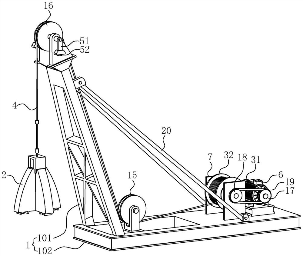
[0047] refer to figure 1 with figure 2 , a percussion drilling cast-in-situ pile construction device, comprising a frame 1, a drill hammer 2, a driving mechanism and a pull rope 4, wherein the frame 1 includes a base 101 and a support 102, and the bottom end of the support 102 is welded and fixed on the base 101, and the angle between the support 102 and the base 101 is an obtuse angle. Two connecting rods 20 are welded and fixed between the upper part of the support 102 and the base 101, so that a triangle is formed between the base 101, the support 102 and the connecting rods 20, so that the structure of the frame 1 is more stable. In other applications, the bottom end of the support 102 is rotatably connected to the base 101, and the upper part of the support 102 is rotatably connected to a connecting rod 20, and the end of the connecting rod 20 away from the support 102 can be fixed on the base 101 by bolts; When installing the frame 1, the free end of the support 102 c...

Embodiment 2

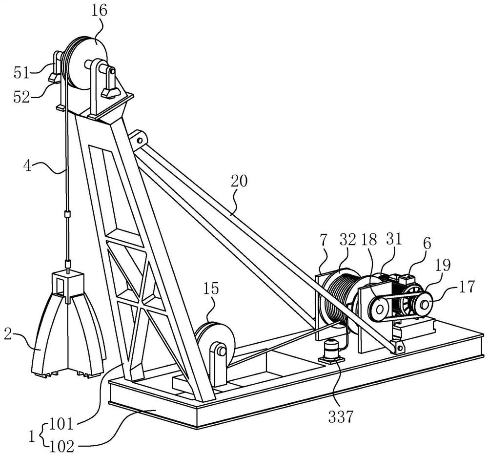
[0056] refer to image 3 with Figure 4 , The difference between this embodiment and Embodiment 1 is that the blocking assembly includes a gear 334, a blocking bar 335, an air bag 336 and an air pump 337, and the side of the support frame 7 is welded with a guide ring 11 and a restricting ring 12, and the restricting ring 12 Located outside the guide ring 11, wherein the air bag 336 is annular, and the air bag 336 is located between the guide ring 11 and the restriction ring 12, that is, the restriction cavity for the air bag 336 is formed between the guide ring 11, the restriction ring 12 and the support frame 7. The air pump 337 is fixed on the base 101 by bolts, the air outlet of the air pump 337 communicates with the air bag 336 through a hose, and the air bag 336 can be inflated and deflated by the air pump 337 .

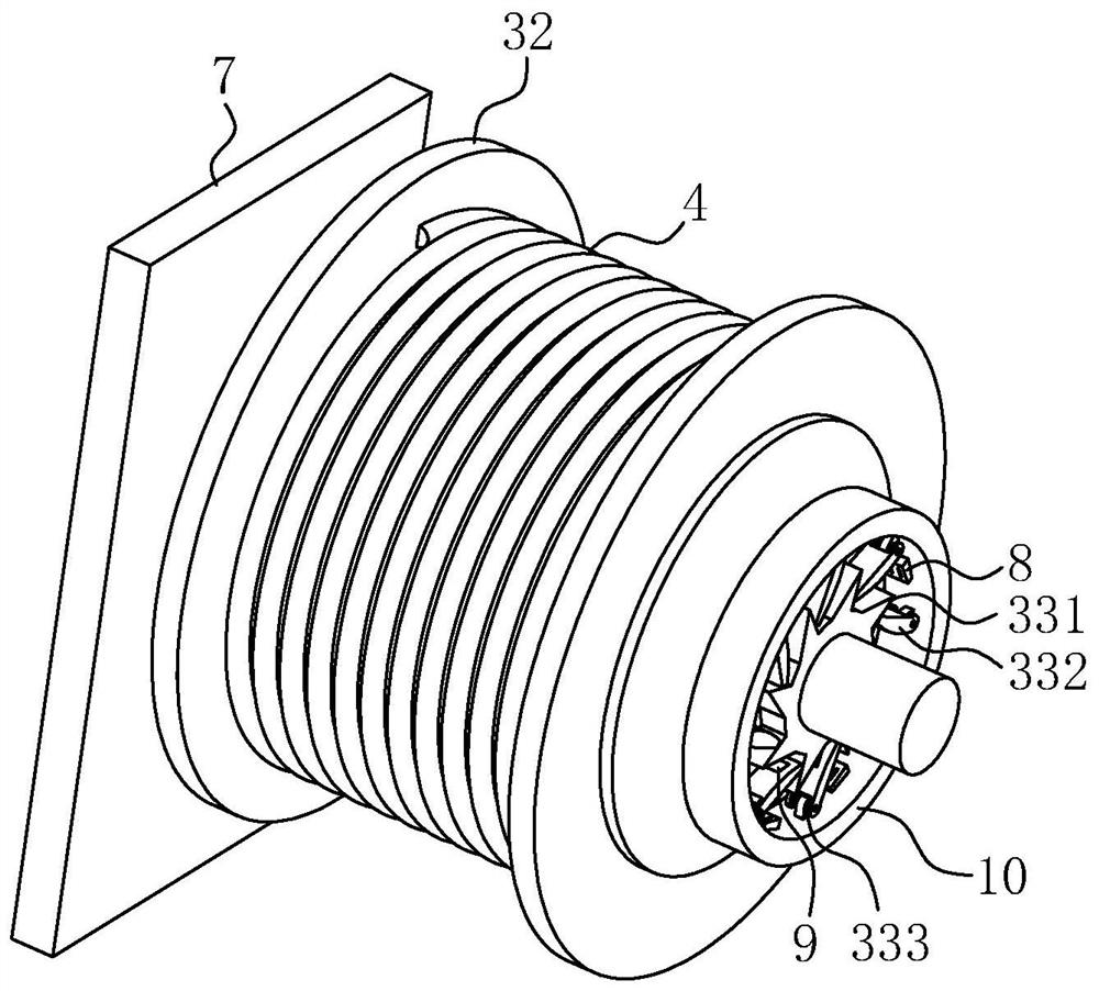
[0057] The gear 334 is fixed on the rotating shaft of the reel 32 by bolts. The guide ring 11 is provided with a plurality of sliding holes 13 , and the plura...


PUM

PropertyMeasurementUnit
Thicknessaaaaaaaaaa
Thicknessaaaaaaaaaa

Abstract

The invention relates to a percussion drill cast-in-place pile construction device. The construction device comprises a rack, a drill hammer, a driving mechanism and a traction rope, wherein a monitoring mechanism and a control mechanism are arranged on the rack, the monitoring mechanism is used for monitoring the deviation angle of the section, close to the drill hammer, of the traction rope, thecontrol mechanism is used for controlling the driving mechanism to prevent the traction rope from being released, the monitoring mechanism comprises a vertical auxiliary part, a distance testing unitand an angle calculating unit, the vertical auxiliary piece is hung on the rack, the distance testing unit is arranged at the free end of the vertical auxiliary piece and used for testing the horizontal distance between the free end of the vertical auxiliary piece and the section, close to the drill hammer, of the traction rope to serve as the offset distance, and the angle calculating unit is connected with the distance testing unit and is used for receiving the offset distance and calculating an offset angle according to the offset distance and a preset calculation formula. The constructiondevice has the effect of enabling the inclination angle of a pile hole to be within the specified inclination range so as to improve the construction quality of the pile foundation.

Description

technical field [0001] The present application relates to the technical field of building construction, in particular to a percussion drilling cast-in-place pile construction device and a construction method thereof. Background technique [0002] Bored pile refers to the pile foundation formed by forming a pile hole in the foundation soil by means of mechanical drilling, punching, steel pipe extrusion or manual excavation on the project site, and placing a steel cage in it and pouring concrete. Bored piles are widely used in engineering projects with poor geological conditions due to their mature construction technology, high bearing capacity, and few restrictions on use. Improving the hole-forming efficiency under the premise of maintaining the stability of the hole wall is an important index to evaluate the pros and cons of impact-hole-forming cast-in-place piles. [0003] When the percussion drill is used to construct the pile foundation of the bored pile, due to the vib...

Claims


Application Information

Patent Timeline
IPC IPC(8): E02D5/34E02D13/00E02D13/06E21B1/04
CPCE02D5/34E02D13/00E02D13/06E21B1/02
Inventor 詹伟秦镜明尹涛
Owner SICHUAN QIANKUN CONSTR GRP CO LTD
Why Eureka
Try Eureka