
A new bolt device with self-deformation and surrounding rock displacement display function

A display function, self-deformation technology, applied in the installation of bolts, mining devices, mining equipment, etc., can solve problems such as failure to optimize bolts, large deformation of surrounding rock, support rupture, etc., to improve convenience and practicability, Accurate effect of surrounding rock deformation data

Active Publication Date: 2022-05-24
CHINA RAILWAY TUNNEL GROUP CO LTD +1
View PDF0 Cites 0 Cited by
  • Summary
  • Abstract
  • Description
  • Claims
  • Application Information

AI Technical Summary

Problems solved by technology

[0002] Anchor is the most basic part of roadway support in contemporary coal mines. It reinforces the surrounding rock of the roadway so that the surrounding rock can support itself. Now the bolt is not only used in mines, but also in engineering technology. Reinforce the main body of slopes, tunnels, and dams. During the tunnel construction process, changes in the displacement of the surrounding rock of the tunnel will seriously affect the safety of the construction. Large deformations of the surrounding rock will lead to the rupture of the primary support. Distortion occurs, so the displacement of the surrounding rock needs to be monitored to ensure construction safety. However, the existing displacement testing device can only reflect the relative deformation of the bolt relative to the surrounding rock, and cannot reflect the situation under the condition that the bolt and the surrounding rock move synchronously. Absolute displacement, which leads to inaccurate deformation data of the surrounding rock, can not truly analyze the stress and deformation of the bolt, that is, cannot optimize the role of the bolt in the surrounding rock support system; comes with a data analysis system and an electronic display

Method used


Image

  • A new bolt device with self-deformation and surrounding rock displacement display function
  • A new bolt device with self-deformation and surrounding rock displacement display function
  • A new bolt device with self-deformation and surrounding rock displacement display function

Examples


Embodiment Construction

[0026] In order to make those skilled in the art better understand the technical solutions of the present invention, the present invention will be further described in detail below with reference to the accompanying drawings.

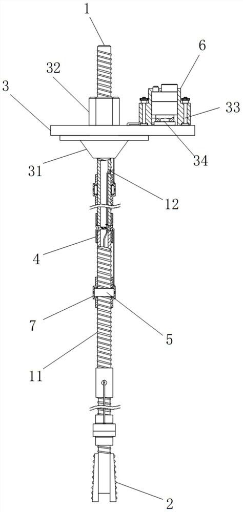
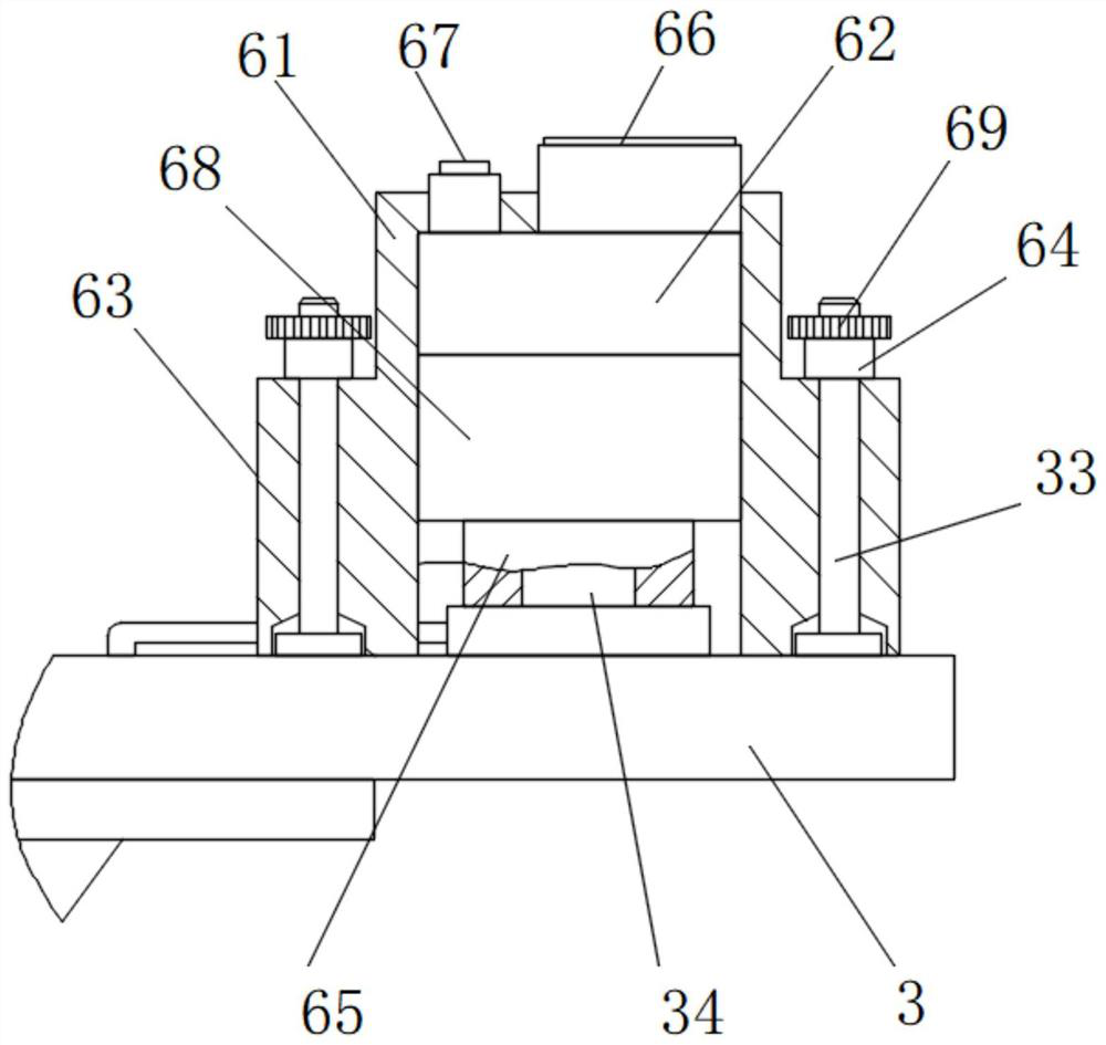
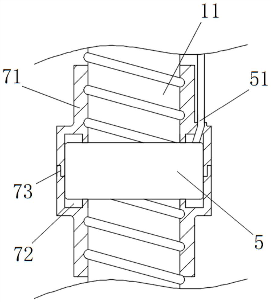
[0027] The present invention provides such as Figure 1-4 Shown is a new type of bolt device with self-deformation and surrounding rock displacement display functions, including a hollow bolt main body 1, the bottom end of the hollow bolt main body 1 is fixedly installed with an anchor head 2, and the hollow bolt main body 1 is fixedly installed with an anchor head 2. A backing plate 3 is slidably provided at the top of the backing plate 3, a slurry stopper 31 is installed on the bottom side of the backing plate 3, an anchor nut 32 is provided on the top of the backing plate 3, and the outer wall of the hollow bolt main body 1 is provided with Spiral protrusion, the anchor nut 32 is threadedly connected with the hollow anchor rod main body 1 through the...


PUM


Abstract

The invention discloses a novel bolt device with functions of self-deformation and surrounding rock displacement display, comprising a hollow bolt main body, an anchor head is fixedly installed at the bottom end of the hollow bolt main body, and A backing plate is slidably arranged, and a grout stopper is installed on the bottom side of the backing plate, and an anchor nut is arranged on the top of the backing plate, and a spiral protrusion is arranged on the outer wall of the hollow anchor rod body, and the anchor nut The spiral protrusion is threadedly connected with the main body of the hollow anchor rod, and the main body of the hollow anchor rod includes a plurality of unit anchor rods. The invention adjusts the position of multiple displacement monitoring sensors by installing the displacement monitoring sensor between the two half-sleeves, so that the displacement monitoring sensor and the hollow bolt main body form an integral body, so that the deformation of the surrounding rock drives the hollow bolt main body When deforming, it can intuitively reflect the absolute displacement under the condition that the bolt and surrounding rock move synchronously.

Description

technical field [0001] The invention relates to the technical field of bolts, in particular to a novel bolt device with self-deformation and surrounding rock displacement display functions. Background technique [0002] The bolt is the most basic component of roadway support in contemporary coal mines. It reinforces the surrounding rock of the roadway so that the surrounding rock supports itself. Now the bolt is not only used in mines, but also in engineering technology. Reinforce the main body of slopes, tunnels and dams. During the construction of the tunnel, the change of the displacement of the surrounding rock of the tunnel will seriously affect the safety of the construction. The large deformation of the surrounding rock will cause the initial support to rupture and the steel frame Distortion and deformation occur. Therefore, it is necessary to monitor the displacement of the surrounding rock to ensure construction safety. However, the existing displacement testing dev...

Claims


Application Information

Patent Timeline
Patent Type & Authority Patents(China)
IPC IPC(8): E21D21/00E21D21/02E21F17/18
CPCE21D21/0026E21D21/008E21D21/0093E21D21/0086E21D21/02E21F17/18
Inventor 杨露伟马亮冯欢欢王亚锋张兵曹耀祖张艳军陈阳宿源麟孙六成刘海峰
Owner CHINA RAILWAY TUNNEL GROUP CO LTD
Learn More