Multifunctional gearbox shell special for three-dimensional parking space
A multifunctional gearbox and three-dimensional parking technology, applied in the field of gearboxes, can solve problems such as easy oil leakage, poor sealing, troublesome oiling, etc., and achieve the effect of ensuring normal operation
- Summary
- Abstract
- Description
- Claims
- Application Information
AI Technical Summary
Problems solved by technology
Method used
Image

Examples
Embodiment 1
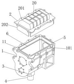
[0033] see Figure 1-10 , a special multifunctional gearbox housing for a three-dimensional parking space of the present invention, comprising a gearbox casing 1 and a sealing cover 2, strip-shaped insertion holes 5 are provided on the four end faces of the top of the gearbox casing 1, and the speed change On the four surfaces of the inner wall of the box housing 1 and near the top, there are bar-shaped return channels 6, the bottom of the bar-shaped insertion hole 5 communicates with the top of the bar-shaped return channel 6, and the top of the gearbox housing 1 There is a communication hole 22 at the bottom and close to the front. The bottom of the gearbox housing 1 and the position at the bottom of the communication hole 22 are integrally formed with a connecting block 3. The inner cavity of the connecting block 3 is provided with a butt joint groove 19 along the ring. The connecting block 3 is threadedly connected with the liquid storage cylinder 4 through the docking gro...
Embodiment 2
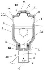
[0035] see Figure 2-7 The left side of the liquid storage cylinder 4 is fixedly connected with a liquid infusion tube 401, and one end of the liquid infusion tube 401 is connected to the inner cavity of the liquid storage cylinder 4, and the other end is movably inserted with a sealing plug 402, and the liquid suction pump 7 is connected with the liquid suction port and The liquid outlet port, the liquid outlet port of the suction pump 7 is connected with a liquid outlet pipe 8, and the top of the pipe body of the liquid outlet pipe 8 is engraved with threads; One end of the shunt pipe 11 penetrates to the left side of the inner cavity of the gearbox housing 1 and extends from the left side of the top of the gearbox housing 1. The other end of the shunt pipe 11 penetrates to the right side of the inner cavity of the gearbox housing 1 and extends from the The right side of the top of the gearbox housing 1 extends out, and the bottom of the shunt pipe 11 is fixedly connected wi...
Embodiment 3
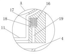
[0037] see Figure 2-3 , the inner chamber of the connecting block 3 and the position at the top of the docking groove 19 are provided with a compression groove 16 along the ring, and the inner chamber of the compression groove 16 is fixedly connected with the compression springs 17 along the ring equidistant, and the bottoms of the plurality of compression springs 17 are fixed A ring-shaped stop block 18 is connected; the appearance of this design can exert a reverse thrust on the liquid storage cylinder 4 screwed into the docking groove 19, and then make the liquid storage cylinder 4 more connected in the docking groove 19. The stability of the device ensures the normal operation of the device; the limit pad 18 is made of a sealing rubber sheet, and the bottom of the limit pad 18 is attached to the connection between the docking groove 19 and the compression groove 16. The appearance of this design, The sealing performance after the liquid storage cylinder 4 is connected in ...
PUM
 Abstract
Description
Claims
Application Information
 - Generate Ideas
- Intellectual Property
- Life Sciences
- Materials
- Tech Scout
- Unparalleled Data Quality
- Higher Quality Content
- 60% Fewer Hallucinations
Browse by: Latest US Patents, China's latest patents, Technical Efficacy Thesaurus, Application Domain, Technology Topic, Popular Technical Reports.
© 2025 PatSnap. All rights reserved.Legal|Privacy policy|Modern Slavery Act Transparency Statement|Sitemap|About US| Contact US: help@patsnap.com