
Control method, device, device and code scanning device for locating light of code scanning equipment

A control method and technology for positioning lights, applied in the computer field, can solve the problems of bright light spots in the graphic code area, graphic code decoding failure, high current, etc., and achieve the effect of reducing energy consumption

Active Publication Date: 2022-07-19
ALIPAY (HANGZHOU) INFORMATION TECH CO LTD
View PDF0 Cites 0 Cited by
  • Summary
  • Abstract
  • Description
  • Claims
  • Application Information

AI Technical Summary

Problems solved by technology

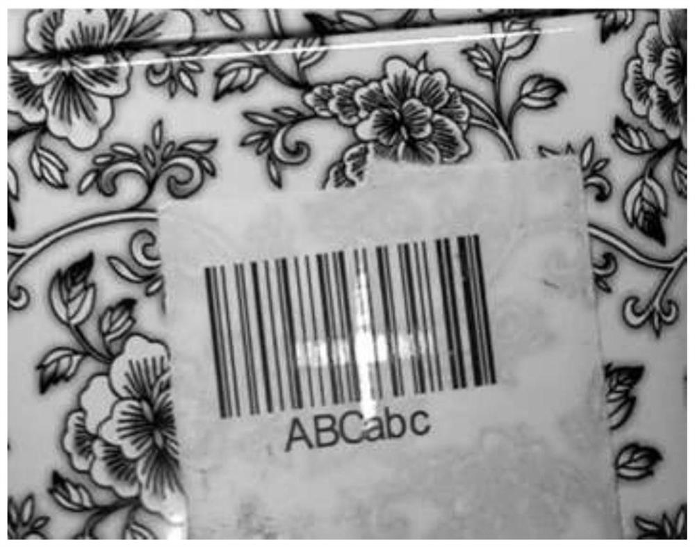
Generally, the brightness of the positioning light is relatively large, which requires higher current, higher power consumption and heat dissipation requirements, and may cause brighter spots in the area of ​​​​the graphic code, which affects the recognition speed of the graphic code, and even causes the decoding of the graphic code to fail.

Method used


Image

  • Control method, device, device and code scanning device for locating light of code scanning equipment
  • Control method, device, device and code scanning device for locating light of code scanning equipment
  • Control method, device, device and code scanning device for locating light of code scanning equipment

Examples


Embodiment Construction

[0024] In order to make those skilled in the art better understand the technical solutions in this specification, the technical solutions in the embodiments of this specification will be clearly and completely described below with reference to the accompanying drawings in the embodiments of this specification. Obviously, the described The embodiments are only some of the embodiments of the present specification, but not all of the embodiments. Based on the embodiments in this specification, all other embodiments obtained by persons of ordinary skill in the art without creative efforts shall fall within the protection scope of this specification.

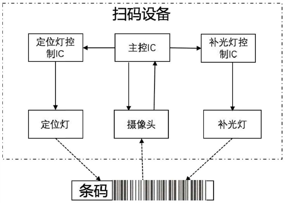
[0025] figure 1 is a schematic structural diagram of a code scanning device in an embodiment of this specification, such as figure 1 As shown, the code scanning device in the embodiment of this specification may include a positioning light control chip (ie, a positioning light IC (Integrated Circuit Chip)), a main control chip (ie, ...


PUM


Abstract

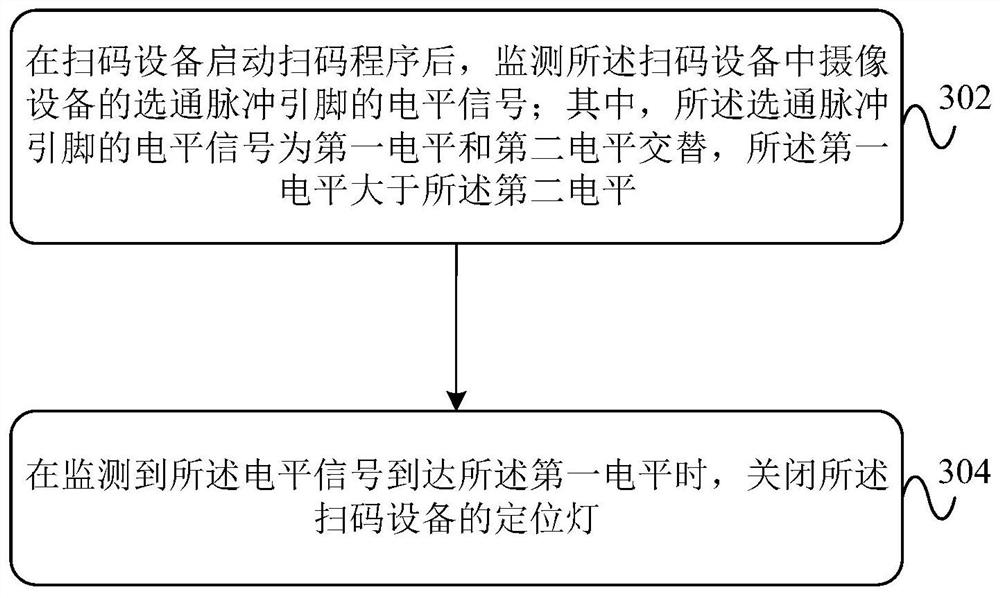
This specification provides a control method, device, device and code scanning device for a positioning light of a code scanning device. The method can monitor the level signal of the strobe pulse pin of the camera device in the code scanning device. When the foot reaches a high level, the positioning light is turned off, which reduces the energy consumption caused by the positioning light under the premise that the camera equipment completes the positioning function. Affects the scanning effect of graphic code images.

Description

technical field [0001] This specification belongs to the field of computer technology, and in particular relates to a control method, device, device and code scanning device for a positioning light of a code scanning device. Background technique [0002] With the popularization of graphic code technology and mobile payment, one-dimensional code, two-dimensional code and other graphic code recognition have been gradually applied to various industries in society, and code scanning equipment has also been widely used. At present, the mainstream technology of graphic code recognition is to perform optical imaging through a CMOS (Complementary Metal Oxide Semiconductor) camera module, and then perform decoding by a back-end main control IC (Integrated Circuit Chip). [0003] Generally, the scanning device includes a positioning light, which is mainly used to locate the graphic code, so that the scanning device can completely capture the image of the graphic code area, and then de...

Claims


Application Information

Patent Timeline
Patent Type & Authority Patents(China)
IPC IPC(8): G06K7/14
CPCG06K7/146G06K7/1408
Inventor 谭世恒陈家大吕俊杰邵黎明刘会淼
Owner ALIPAY (HANGZHOU) INFORMATION TECH CO LTD
Learn More