
Single-shaft winding machine

A technology of winding machine and winding mechanism, which is applied in coil manufacturing, electrical components, inductance/transformer/magnet manufacturing, etc. It can solve the problems of reducing production efficiency and product quality, failing to achieve a high degree of automation, and difficult to accurately grasp the position. , to achieve the effect of improving yield rate, facilitating welding operation and high spot welding efficiency

Inactive Publication Date: 2021-03-12
苏州同岸精工科技有限公司
View PDF0 Cites 0 Cited by
  • Summary
  • Abstract
  • Description
  • Claims
  • Application Information

AI Technical Summary

Problems solved by technology

In the traditional process, the process of winding the inductor and spot welding the polar lines is extremely complicated
In addition, during manual operation, the winding efficiency is low, and it is difficult to accurately grasp the position of the pole line after it is turned over, which greatly affects the spot welding operation
Common winding machines on the market are generally unable to achieve a high degree of automation, which greatly reduces production efficiency and product quality

Method used


Image

  • Single-shaft winding machine
  • Single-shaft winding machine
  • Single-shaft winding machine

Examples


Embodiment

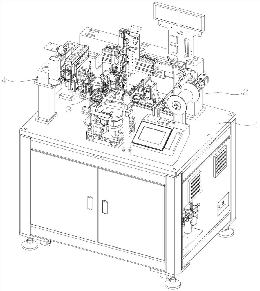
[0040] refer to Figure 1 to Figure 8 As shown, the invention discloses a single-axis winding machine, comprising:

[0041] The chassis 1 and the flying fork double-layer winding mechanism 2 , the inductance polar line turning mechanism 3 and the winding induction welding mechanism 4 arranged on the chassis 1 .

[0042] Among them, the flying fork double-layer winding mechanism 2 includes a polar line outlet unit, a flying fork unit, a cutting unit that can cut the polar line and pull a new polar line to the flying fork unit, and a conveying unit that clamps and delivers the inductance .

[0043] Preferably, the pole line outlet unit includes several roller shaft assemblies with different heights for adjusting the tension of the pole line, which can well improve the quality of the outgoing line, thereby improving the quality of the upper line.

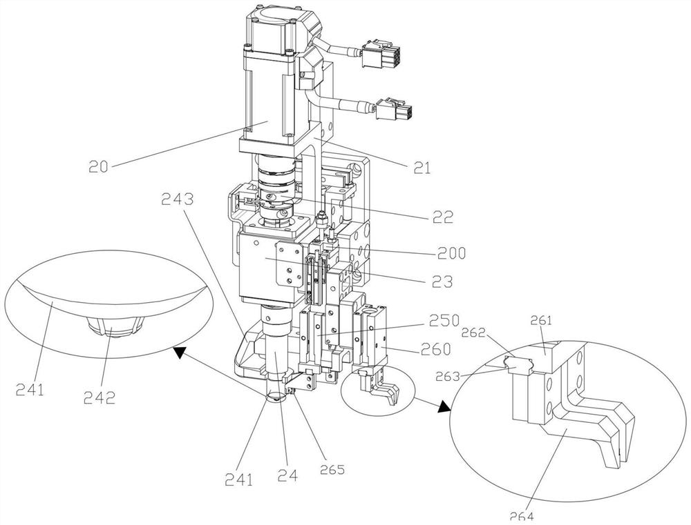
[0044] Preferably, the conveying unit includes a clamping and rotating drive source 20, the above-mentioned clamping and rotating d...


PUM


Abstract

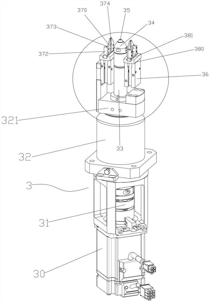
The invention discloses a single-shaft winding machine which comprises a case, a flying fork double-layer winding mechanism, an inductance pole wire overturning mechanism and a winding inductor welding mechanism. The flying fork double-layer winding mechanism, the inductance pole wire overturning mechanism and the winding inductor welding mechanism are arranged on the case. The flying fork double-layer winding mechanism comprises an electrode wire outlet unit, a flying fork unit, a pulling and cutting unit capable of cutting off an electrode wire and pulling a new electrode wire to the flyingfork unit, and a conveying unit for clamping and conveying an inductor. The inductance pole wire overturning mechanism comprises an inductance clamping unit used for clamping and fixing a winding inductor and a pole wire overturning unit used for clamping and overturning an inductance pole wire. The winding inductor welding mechanism comprises an electrode wire spot welding unit and an inductor discharging unit. Double-layer winding can be automatically carried out on the inductor, an inductor polar line is turned over and welded to the inductor, the automation degree is high, manual operationis not needed, the winding efficiency is high, and the yield of the wound inductor is greatly improved.

Description

technical field [0001] The invention relates to a winding machine, in particular to a single-axis winding machine. Background technique [0002] Wire wound inductors are one of the commonly used components in circuits. [0003] In the production process of wire-wound inductors, the polar wires need to be wound and spot-welded on the inductors. In the traditional process, the process of winding the inductor and spot welding the polar lines is extremely complicated. In addition, during manual operation, the winding efficiency is low, and it is difficult to accurately grasp the position of the pole line after it is flipped, which greatly affects the spot welding operation. Common winding machines currently on the market are generally unable to achieve a high degree of automation, which greatly reduces production efficiency and product quality. [0004] Therefore, it is necessary to design a new single-axis winding machine. Contents of the invention [0005] The technical ...

Claims


Application Information

Patent Timeline
Patent Type & Authority Applications(China)
IPC IPC(8): H01F41/06H01F41/082H01F41/09H01F41/096
CPCH01F41/06H01F41/082H01F41/09H01F41/096
Inventor 王帅
Owner 苏州同岸精工科技有限公司
Learn More