
Card tray ejection mechanism and electronic equipment

Inactive Publication Date: 2021-03-12
WINGTECH COMM
View PDF0 Cites 4 Cited by
  • Summary
  • Abstract
  • Description
  • Claims
  • Application Information

AI Technical Summary

Problems solved by technology

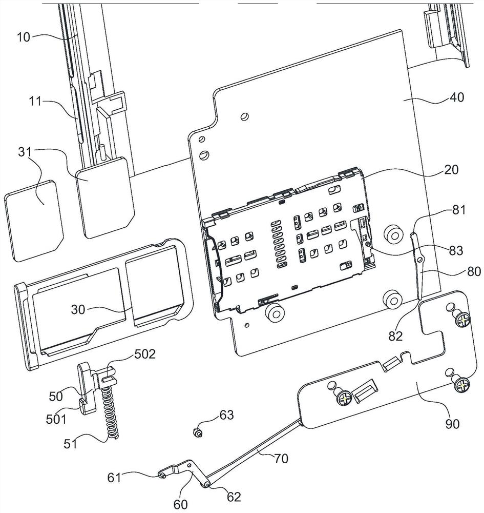
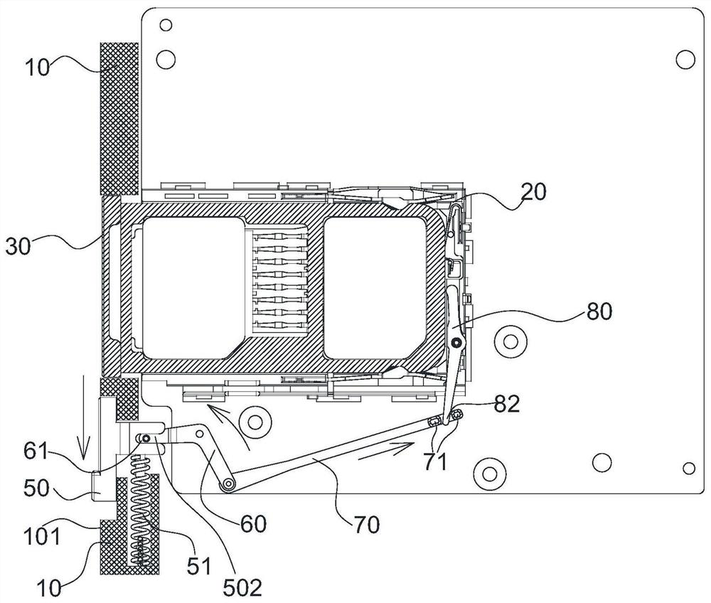
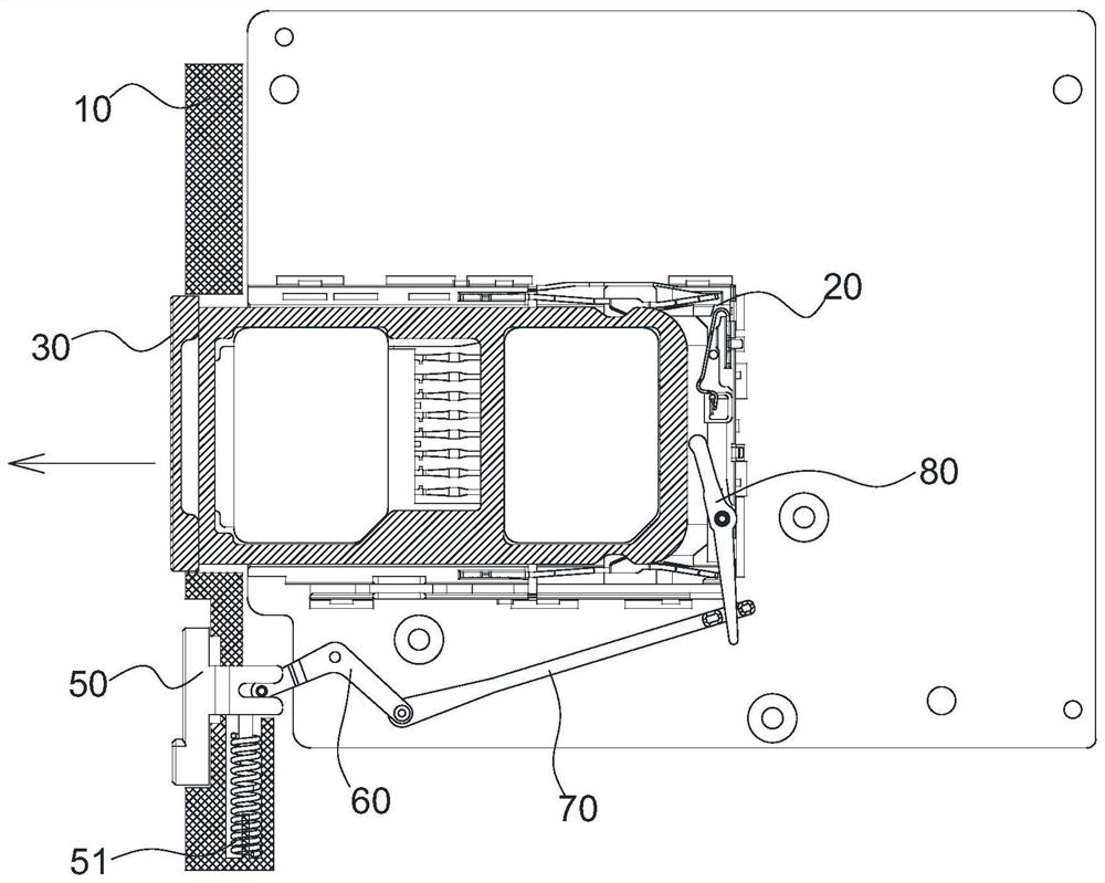
[0002] Electronic devices such as mobile phones and tablets usually need to be loaded with SIM cards and memory cards. Specifically, the SIM card and memory card are installed on the card tray, and then the card tray is inserted into the card slot opened on the housing. The card tray and the card slot The clamping parts provided inside cooperate to make the card holder be fixed in the card slot, preventing the card holder from being separated from the opening of the card slot; the current card holder ejection mechanism is usually provided with a lever and a push rod inside the housing, wherein the lever The rod is set on the inner side of the card tray, the push rod is set on one side of the card tray, and a small hole facing the push rod is opened on the housing. When removing the card, insert the card-taking needle into the small hole and push the push rod , the push rod drives the lever to move, and the card holder is ejected out of the card slot. That is to say, the existing card holder ejection mechanism must use a special card removal needle to eject the card holder. Accessories, not easy to carry around, and easy to lose, making it extremely inconvenient to change cards

Method used


Image

  • Card tray ejection mechanism and electronic equipment
  • Card tray ejection mechanism and electronic equipment
  • Card tray ejection mechanism and electronic equipment

Examples


Embodiment Construction

[0025] The following will clearly and completely describe the technical solutions in the embodiments of the present invention with reference to the accompanying drawings in the embodiments of the present invention. Obviously, the described embodiments are only part of the embodiments of the present invention, not all of them. Based on the embodiments of the present invention, all other embodiments obtained by persons of ordinary skill in the art without creative efforts fall within the protection scope of the present invention.

[0026] It should be noted that all directional indications (such as up, down, left, right, front, back...) in the embodiments of the present invention are only used to explain the relationship between the components in a certain posture (as shown in the accompanying drawings). Relative positional relationship, movement conditions, etc., if the specific posture changes, the directional indication will also change accordingly.

[0027] In addition, the ...


PUM


Abstract

The invention discloses a card tray ejection mechanism and electronic equipment. The card tray ejection mechanism comprises a front shell, a card seat and a card tray, the card seat is located in thefront shell, a groove used for containing the card support is formed in the card seat, an opening right facing the groove is formed in the front shell, and the opening is used for allowing the card support to be inserted into the groove. The card tray ejection mechanism further comprises a push rod, a connecting rod assembly and a toggle key, one end of the push rod forms an ejection part which islocated at the inner side end of the card holder to eject the card holder, two ends of the connecting rod assembly are respectively connected with the other end of the push rod and the toggle key, and the toggle key is installed on the front shell in a sliding mode. And the toggle key is provided with a toggle part exposed out of the surface of the front shell, and the toggle part is used for driving the toggle key to move so as to enable the connecting rod assembly to drive the pushing part of the push rod to move. According to the invention, the card tray can be conveniently and rapidly ejected out only by pushing the toggle key without accessories such as a card pin and the like.

Description

technical field [0001] The invention relates to the field of electronic technology, in particular to a card holder ejecting mechanism and electronic equipment. Background technique [0002] Electronic devices such as mobile phones and tablets usually need to be loaded with SIM cards and memory cards. Specifically, the SIM card and memory card are installed on the card tray, and then the card tray is inserted into the card slot opened on the housing. The card tray and the card slot The clamping parts provided inside cooperate to make the card holder be fixed in the card slot, preventing the card holder from being separated from the opening of the card slot; the current card holder ejection mechanism is usually provided with a lever and a push rod inside the housing, wherein the lever The rod is set on the inner side of the card tray, the push rod is set on one side of the card tray, and a small hole facing the push rod is opened on the housing. When removing the card, insert ...

Claims


Application Information

Patent Timeline
Patent Type & Authority Applications(China)
IPC IPC(8): H01R13/633H01R12/71
CPCH01R12/714H01R12/716H01R13/6335
Inventor 曾荣慧
Owner WINGTECH COMM
Learn More