
High-reliability brushless motor

A reliability and motor technology, applied in the direction of the casing/cover/support, cooling/ventilation device, electrical components, etc., can solve the problems of noise generation, motor burn-in, and reduce the dust collection effect of the vacuum cleaner, so as to improve the use performance , to solve the effect of loud noise

Inactive Publication Date: 2021-03-12
CINDERSON TECH (SUZHOU) CO LTD
View PDF2 Cites 0 Cited by
  • Summary
  • Abstract
  • Description
  • Claims
  • Application Information

AI Technical Summary

Problems solved by technology

[0003] 1. The air enters and exits from the air inlet of the motor, and the external wind dissipates heat through the motor. When the external air enters the motor, due to the complex internal structure of the motor, the noise generated by the air impact is relatively large, resulting in the overall noise of the motor, which greatly affects the The use performance of the vacuum cleaner motor, and the motor part is the ash bucket of the vacuum cleaner when the vacuum cleaner is in the complete machine state, and the air inlet of the motor cannot be sealed. The airflow passing through the motor may cause the ash suction bucket to be completely blocked by dust. Once the motor part If it is completely blocked, the motor will overheat and cause failures such as burn-in, which will reduce the safety performance of the vacuum cleaner motor;
[0004] 2. If the above-mentioned air intake from the motor air inlet is not used, but a separate cooling fan blade is added to dissipate the heat from the motor, the cooling of the motor using the fan blade will still produce noise, and, due to the addition of the fan blade, resulting in The efficiency of the motor is greatly reduced, which reduces the dust collection effect of the vacuum cleaner;

Method used


Image

  • High-reliability brushless motor
  • High-reliability brushless motor
  • High-reliability brushless motor

Examples


Embodiment

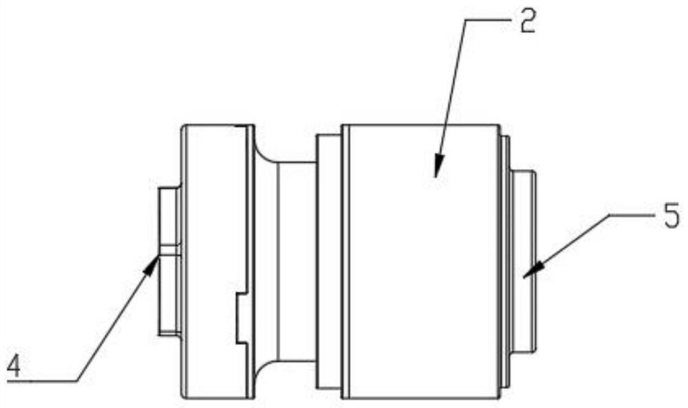
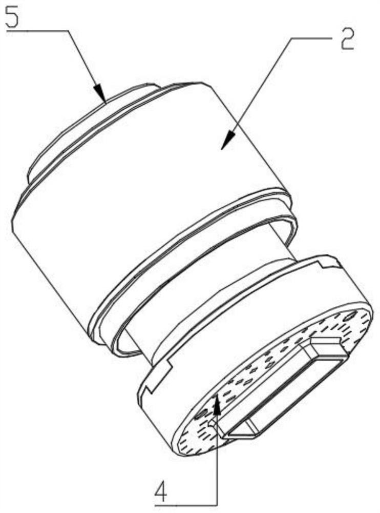
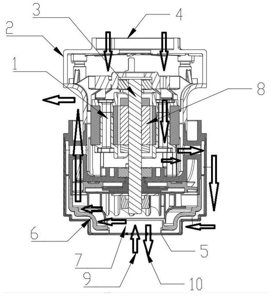
[0029] Example: see Figure 1-3 , the present invention provides a technical solution: a high-reliability brushless motor, including a motor body 1 and a motor casing 2, the motor body 1 has an axially penetrating rotor 3, the motor body 1 is arranged inside the motor casing 2, and the motor casing 2 One end is provided with a top cover 4, the other end of the motor casing 2 is provided with a bottom cover 5, and the rotor 3 is provided with a moving impeller 6;

[0030] There is a negative pressure area 7 at the bottom cover 5, and the negative pressure area 7 is located below the moving impeller 6, and a motor area 8 is provided inside the motor body 1, and the motor area 8 is located above the moving impeller 6;

[0031] There is no mechanical contact and no gap between the motor area 8 and the moving impeller 6;

[0032] The negative pressure area 7 and the moving impeller 6 side form a first airflow pipeline 9 for air circulation;

[0033] The first airflow pipeline 9 r...


PUM


Abstract

The invention discloses a high-reliability brushless motor which comprises a motor main body and a motor shell. An axially-through rotor is arranged in the motor main body, the motor main body is arranged in the motor shell, and a top cover is arranged at one end of the motor shell. A bottom cover is arranged at the other end of the motor shell, and a movable impeller is arranged on the rotor. Themotor is scientific and reasonable in structure and IS safe and convenient to use, compared with an existing mode that air enters from a motor opening to cool the motor, and the phenomenon that airflow impacts the motor is avoided, a motor area is cooled directly through a second airflow pipeline penetrating through the interior of the motor body and by means of the negative pressure generated during operation of the motor. The motor does not generate excessive noise, so that the use performance of the motor is greatly improved.

Description

technical field [0001] The invention relates to the technical field of motors, in particular to a brushless motor with high reliability. Background technique [0002] The brushless motor is composed of the motor body and the driver. It is a mechatronic product. The brushless motor operates in a self-controlled manner. It does not need to start the winding on the rotor like a synchronous motor that starts under heavy load under variable frequency speed regulation. This means that it will not oscillate or lose steps when the load changes suddenly. This is the excellence of the brushless motor. At the same time, the brushless motor also has the characteristics of low noise, high energy efficiency and super durability. It is suitable for use in vacuum cleaners. Motors are mainly divided into two types: dry motors and dry-wet motors. When the vacuum cleaner is working, the motor part and the fan part mainly work. The motor part uses the continuous electromagnetic torque generated...

Claims


Application Information

Patent Timeline
Patent Type & Authority Applications(China)
IPC IPC(8): H02K9/06H02K5/10
CPCH02K5/10H02K9/06
Inventor 朱云舫
Owner CINDERSON TECH (SUZHOU) CO LTD
Learn More