
Optical fiber line detection control method, device and equipment and readable storage medium

An optical fiber line, detection and control technology, applied in the field of optical communication, can solve problems such as waste of detection resources

Pending Publication Date: 2021-03-12
ZTE CORP
View PDF0 Cites 0 Cited by
  • Summary
  • Abstract
  • Description
  • Claims
  • Application Information

AI Technical Summary

Problems solved by technology

[0004] An optical fiber line detection control method, device, equipment, and readable storage medium provided by the embodiments of the present invention solve the problem in the related art that the line detection of the optical fiber line to be detected is cyclically performed according to a fixed detection cycle, resulting in a great waste of detection resources question

Method used


Image

  • Optical fiber line detection control method, device and equipment and readable storage medium
  • Optical fiber line detection control method, device and equipment and readable storage medium
  • Optical fiber line detection control method, device and equipment and readable storage medium

Examples


Embodiment 1

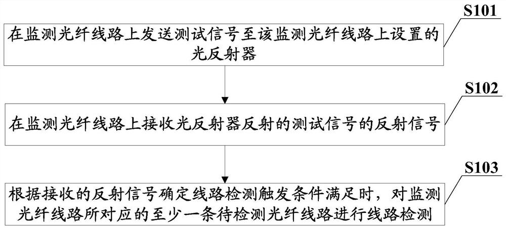
[0033] The optical fiber line detection and control method provided in this embodiment can set a corresponding monitoring optical fiber line for at least one optical fiber line to be detected, and set a reflection signal for reflecting the test signal on the monitoring optical fiber line. According to the monitoring optical fiber line It is determined whether to perform line detection on at least one optical fiber line to be detected corresponding to the monitored optical fiber line according to the reflected signal received on the network, instead of performing line detection according to a fixed detection cycle cycle, the control method is more flexible and reasonable. And because the resources consumed by the transmission of the test signal and the reception and processing of the reflected signal are far less than the resources consumed by the detection of the optical fiber line to be detected, based on monitoring the optical fiber line to be detected and triggering the detec...

Embodiment 2

[0054] This embodiment provides a fiber optic line detection control device, which can be installed in various fiber optic line detection equipment, please refer to image 3 shown, including:

[0055] The reflection measurement module 301 is used to send a test signal on the monitoring optical fiber line to the optical reflector provided on the monitoring optical fiber line, receive the reflected signal of the test signal reflected by the optical reflector, and determine whether the trigger condition for line detection is satisfied according to the reflected signal.

[0056] The line measurement module 302 is configured to perform line detection on at least one optical fiber line to be detected corresponding to the monitored optical fiber line when the reflection measurement module determines that the trigger condition of the line detection is met.

[0057] It should be understood that, in this embodiment, the corresponding relationship between the monitored optical fiber line...

Embodiment 3

[0082] This embodiment also provides a kind of optical fiber line detection equipment, this optical fiber line detection equipment can be used as the equipment of offline or online face search system, see Figure 12 As shown, it includes a processor 1201, a memory 1202 and a communication bus 1203;

[0083] The communication bus 1203 is used to realize the communication connection between the processor 1201 and the memory 1202;

[0084] In an example, the processor 1201 may be configured to execute one or more computer programs stored in the memory 1202, so as to implement the steps of the methods for controlling optical fiber line detection in the above embodiments.

[0085] The present embodiment also provides a computer-readable storage medium, which includes information implemented in any method or technology for storing information, such as computer-readable instructions, data structures, computer program modules, or other data. volatile or nonvolatile, removable or non-...


PUM


Abstract

The embodiment of the invention provides an optical fiber line detection control method, device and equipment and a readable storage medium, and the method comprises the steps: setting a correspondingmonitoring optical fiber line for at least one to-be-detected optical fiber line, setting a reflection signal for reflecting a test signal on the monitoring optical fiber line, and in a monitoring process, when it is determined that the line detection triggering condition is met according to the condition of the reflection signal received on the monitoring optical fiber line, controlling line detection to be conducted on the at least one to-be-detected optical fiber line corresponding to the monitoring optical fiber line, wherein line detection is not conducted circularly according to a fixeddetection period, and the control mode is more flexible and reasonable; since the resources required to be consumed for sending the test signal and receiving and processing the reflection signal arefar less than the resources required to be consumed for detecting the optical fiber line to be detected, triggering the to-be-detected optical fiber line to be subjected to line detection only when required based on monitoring of the monitoring optical fiber line; and increasing the resource utilization rate to a great extent.

Description

technical field [0001] The present invention relates to the field of optical communication, in particular to an optical fiber line detection control method, device, equipment and readable storage medium. Background technique [0002] With the rapid development of optical fiber networks, the maintenance methods of optical fiber quality are becoming more and more important. Effective maintenance methods not only increase the cost at a low cost, but also are easy to deploy and can be actively operated and maintained, that is, when the communication service has not been affected. Potential risks can be quickly identified. The optical time domain reflection detection technology is a technology applied to the performance detection analysis and fault location of optical fiber lines in related technologies. [0003] In the related art, when optical time domain reflectance detection technology is used to detect the optical fiber line to be detected, the fixed detection period is set...

Claims


Application Information

Patent Timeline
IPC IPC(8): H04B10/071
CPCH04B10/071
Inventor 何志敏谢云鹏曹晓建王艳华
Owner ZTE CORP
Learn More