
A heat dissipation assembly structure of a switching power supply

A technology of assembly structure and switching power supply, which is applied to the structural parts of electrical equipment, electrical components, cooling/ventilation/heating transformation, etc., can solve the problems of time-consuming and labor-consuming, low installation efficiency, dust accumulation in heat dissipation structure, etc., and achieve improvement Heat dissipation effect, high installation efficiency and stable structure

Active Publication Date: 2021-08-06
达州市天宝锦湖电子有限公司
View PDF0 Cites 0 Cited by
  • Summary
  • Abstract
  • Description
  • Claims
  • Application Information

AI Technical Summary

Problems solved by technology

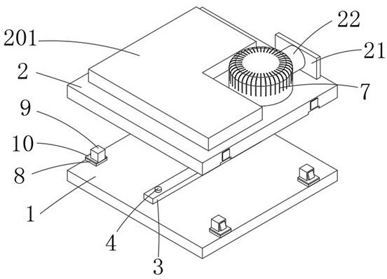
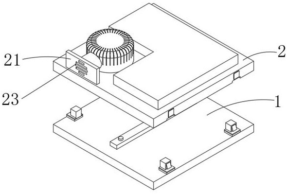
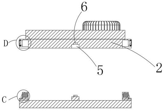
[0003] The purpose of the present invention is to provide a heat dissipation assembly structure for switching power supply. By setting a fixed plate, a fixed column, a plate groove and a column groove, the existing installation plate has no positioning device during installation, and the problem that shaking is easy to affect the installation is solved; Set up posts, slots, spring slots, first springs and card slots, which solves the problem that the existing mounting plate and bracket need to be fixed by screws, resulting in low installation efficiency, time-consuming and labor-intensive problems; by setting the baffle , air intake slot, deflector and adsorption layer, which solves the problem of serious dust accumulation in the heat dissipation structure under long-term use and affects the heat dissipation; by setting the cooling fan, the problem of general heat dissipation effect of the heat dissipation mechanism is solved; by setting the rotating groove and the rotating shaft , rotating blades and brush heads, which solve the problem that the heat dissipation structure needs to be disassembled and cleaned after dust accumulation

Method used


Image

  • A heat dissipation assembly structure of a switching power supply
  • A heat dissipation assembly structure of a switching power supply
  • A heat dissipation assembly structure of a switching power supply

Examples


Embodiment

[0038] Embodiment: When installing the mounting plate 2, the fixing plate 3 snaps into the plate groove 5, and the fixing plate 3 limits the mounting plate 2 to prevent the mounting plate 2 from shaking during installation. At the same time, the fixing column 4 snaps into the column groove 6 to lift The fixing effect of the fixing plate 3, the post 9 is inserted in the slot 15, the backing plate 8 is used for auxiliary fixing, the buffer pad 10 improves the cushioning effect, when the post 9 is inserted into the slot 15, the block 13 is squeezed by the slot 15, the second A spring 12 is deformed, and the block 13 is pressed into the spring slot 11. When the post 9 is fully inserted, the position of the spring slot 11 is aligned with the slot 16, the first spring 12 recovers, and the block 13 pops out, and the slot 13 is aligned with the slot. 16 snap fit, firmly fix the mounting plate 2 and the support frame 1; when it is necessary to disassemble the mounting plate 2 and the su...


PUM


Abstract

The invention discloses a heat dissipation assembly structure of a switching power supply, and relates to the technical field of assembly structures. The invention comprises a support frame and a mounting plate, a heat dissipation mechanism is arranged on the upper surface of the mounting plate, a fixed plate is fixedly connected to the upper surface of the support frame, a plate groove is arranged on the bottom surface of the mounting plate, a plurality of backing plates are fixedly connected to the upper surface of the support frame, and a plurality of backing plates The center line of the support frame is arranged symmetrically, the upper surface of the backing plate is fixedly connected with the inserting column, the bottom surface of the mounting plate is provided with a number of pad grooves, the inner surface of the pad groove is provided with slots, the upper surface of the mounting plate is provided with a baffle, and the surface of the baffle is provided There are air intake slots. The present invention saves the conventional screw fixing method of the mounting plate by setting the fixing plate, the plate groove, the inserting column, the slot and the air intake groove, so that the installation efficiency of the structure is higher, the structure is stable after installation, and the heat dissipation effect is better at the same time. The dust-proof effect is better, and there is no need for users to clean up the dust afterwards.

Description

technical field [0001] The invention belongs to the field of assembly structures, in particular to a cooling assembly structure for switching power supplies. Background technique [0002] At present, the existing switching power supply needs to set the MOS, rectifier bridge, Schottky diode and other heating components separately on a heat dissipation structure. The switching power supply mounting plate is locked on the bracket by screws. There is no positioning device between the mounting plate and the bracket, and it is easy to shake when fixed, which affects the installation efficiency and consumes time and energy; the heat dissipation effect is average, and the heat dissipation structure is easy to accumulate dust under long-term use, which has a certain impact on heat dissipation. After dust accumulation, it needs to be disassembled and cleaned; therefore, a heat dissipation assembly structure of switching power supply is proposed. Contents of the invention [0003] T...

Claims


Application Information

Patent Timeline
Patent Type & Authority Patents(China)
IPC IPC(8): H05K7/20B08B1/00
CPCH05K7/20136B08B1/12
Inventor 姜晏斌
Owner 达州市天宝锦湖电子有限公司
Learn More