Novel adjustable intramedullary nail

An intramedullary nail and adjustable technology, applied in the field of new adjustable intramedullary nails, can solve the problems of inability to firmly fix fractured bones, delayed union of fracture ends, large diameter of the nail body, etc., to shorten fixation time, accelerate fracture healing, Fixed easy effects

Pending Publication Date: 2021-03-16
宋若怡
View PDF0 Cites 0 Cited by
  • Summary
  • Abstract
  • Description
  • Claims
  • Application Information

AI Technical Summary

Problems solved by technology

[0003] The purpose of the present invention is to provide a new type of adjustable intramedullary nail to solve the above-mentioned background technology when using a normal intramedullary nail, the diameter of the nail body is too large, especially the distal side cannot be locked with a bone screw, and only one side can be locked. Locked fractures, resulting in the inability to firmly fix the fractured bones, prone to the disadvantages of loss of reduction, displacement of fractures, delayed union of fracture ends, and nonunion

Method used


Image

  • Novel adjustable intramedullary nail
  • Novel adjustable intramedullary nail
  • Novel adjustable intramedullary nail

Examples


Embodiment 1

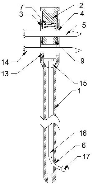
[0032] Example 1, such as figure 1 As shown, a novel adjustable intramedullary nail includes a main nail of the intramedullary nail, the main nail of the intramedullary nail is a hollow structure, and the main nail of the intramedullary nail includes a proximal end 3 of the intramedullary nail and a main body of the intramedullary nail 1 , the proximal end 3 of the intramedullary nail and the main body 1 of the intramedullary nail are integrally structured, the diameter of the proximal end 3 of the intramedullary nail is greater than the diameter of the main body 1 of the intramedullary nail, and the proximal end 3 of the intramedullary nail is provided with two The penetrating power screw holes are the upper power screw hole 4 and the lower power screw hole 13 respectively, in which the upper power bone screw 5 and the lower power bone screw 14 are installed respectively, and can move up and down along the power screw holes. An adjustment hole 6 is provided at the distal end ...

Embodiment 2

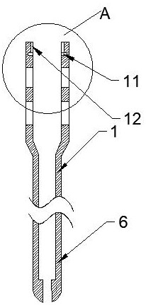
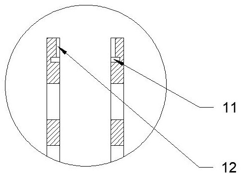
[0037] Example 2, such as figure 2 , image 3 , Figure 4 As shown, the difference between this embodiment and Embodiment 1 lies in the connection mode between the tail cap 2 and the proximal end 3 of the intramedullary nail. The groove 11 communicates with a vertical guide groove 12 . The tail cap 2 is provided with a protrusion 10 , and the protrusion 10 can slide up and down along the vertical guide groove 12 and can rotate along the annular groove 11 .

Embodiment 3

[0038] Example 3, such as Figure 5 As shown, the difference between this embodiment and Embodiment 1 is that the pressure regulating spring 1 is replaced by an elastic balloon 19 , and a balloon base is arranged under the elastic balloon 19 .


PUM


Abstract

The invention discloses a novel adjustable intramedullary nail. The intramedullary nail comprises an intramedullary nail main nail of a hollow structure, and the intramedullary nail main nail comprises an intramedullary nail near end and an intramedullary nail body; the intramedullary nail near end and the intramedullary nail body are of an integrated structure, and the diameter of the intramedullary nail near end is larger than that of the intramedullary nail body. A plurality of through power screw holes are formed in the intramedullary nail near end. An adjusting hole is formed in the portion, away from the near end of the intramedullary nail, of the intramedullary nail body. Power bone screws are installed in the power screw holes and can move in the axial direction of the power screwholes. A tail cap is installed on the side of the intramedullary nail near end, a first elastomer is arranged between the tail cap and one power bone screw, and an absorbable gasket is arranged on thefar side of the power bone screw, and supports the power bone screw. An adjusting device for adjusting the stress of the fracture end is arranged on the intramedullary nail body, and can adjust the stress of the fracture end according to the specific situation of a fracture. Stress shielding of the fracture end is avoided, fracture healing is accelerated, delayed healing and non-healing of the fracture are reduced, and the occurrence rate of re-fracture after the intramedullary nail is removed is reduced.

Description

technical field [0001] The invention belongs to the field of medical devices, and in particular relates to a novel adjustable intramedullary nail. Background technique [0002] Bone plate and intramedullary nail internal fixation have been used clinically for many years. There are many methods for fracture fixation, among which intramedullary nail fixation is one of the most commonly used methods. The traditional intramedullary nail is to fix the fracture The bone is fixed on the intramedullary nail by screws, so that the intramedullary nail and the bone are integrated, but in the later stage of fracture repair, due to the stress shielding effect of the intramedullary nail, it is impossible to give suitable stress stimulation to the fracture end, and delayed bone union and nonunion are prone to occur , Slow bone mineralization, long internal fixation time, fracture after removal of the intramedullary nail and other disadvantages limit its popularization and application. Esp...

Claims


Application Information

Patent Timeline
Patent Type & Authority Applications(China)
IPC IPC(8): A61B17/72
CPCA61B17/72A61B17/7233A61B17/7291
Inventor 宋文超王秋霞宋若怡李兴华王俊文王军强徐蕾严立张培训禹宝庆刘光耀郑宪友肖海军张堃崔永光李正勋张铠张胜利毕荣修宋健李中锋刘中何张树明李明任秀智李志杰郭树章李明东刘鸣江陈明陈宇杰林涨源张志宏李百川董桂贤郭琰贾逢爽汤武兵桑锡光刘士懂朱勇郭书权聂涛郑诚功张学森
Owner 宋若怡
Why Eureka
Try Eureka