Single-roller coating machine

A technology of coating machine and single roller, which is applied in the direction of coating, liquid coating device on the surface, etc. It can solve the problems of many moving parts, long time for changing rollers, affecting the rigidity of coating rollers, etc., so as to ensure the structural rigidity and stability performance, reduce maintenance costs, and improve maintenance efficiency

Pending Publication Date: 2021-03-16
WISDRI ENG & RES INC LTD
View PDF0 Cites 1 Cited by
  • Summary
  • Abstract
  • Description
  • Claims
  • Application Information

AI Technical Summary

Problems solved by technology

This roll change process has many moving parts and takes a long time to change rolls, which has a certain impact on the production rhythm and cost. At the same time, the coating liquid will be spilled around the coating machine, causing certain environmental pollution; moreover, in order to enter and exit the belt The rigidity of the opening of the "C" frame designed with steel is poor, which indirectly affects the rigidity of the coating roller and affects the uniformity of the coating on the operation side and the transmission side, and the movement of the "C" frame is also difficult. It will indirectly affect the installation and positioning accuracy of the upper coating roller and the lower coating roller, and affect the accuracy of the coating thickness

Method used


Image

  • Single-roller coating machine
  • Single-roller coating machine
  • Single-roller coating machine

Examples


Embodiment Construction

[0024] The following clearly and completely describes the technical solutions in the embodiments of the present invention. Obviously, the described embodiments are only some of the embodiments of the present invention, but not all of them. Based on the embodiments of the present invention, all other embodiments obtained by persons of ordinary skill in the art without making creative efforts belong to the protection scope of the present invention.

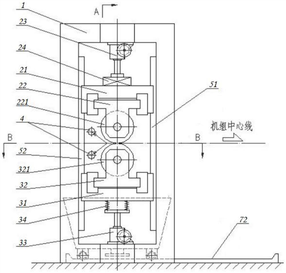
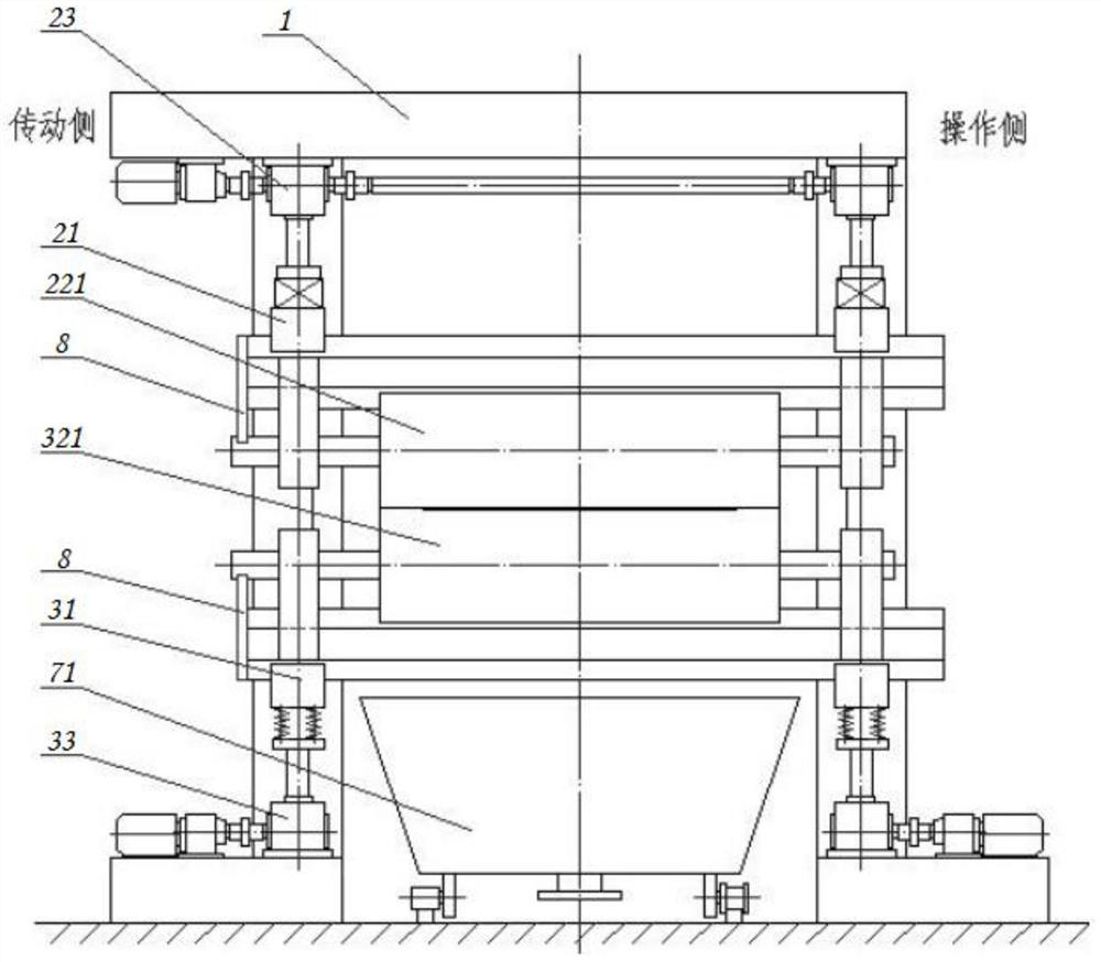
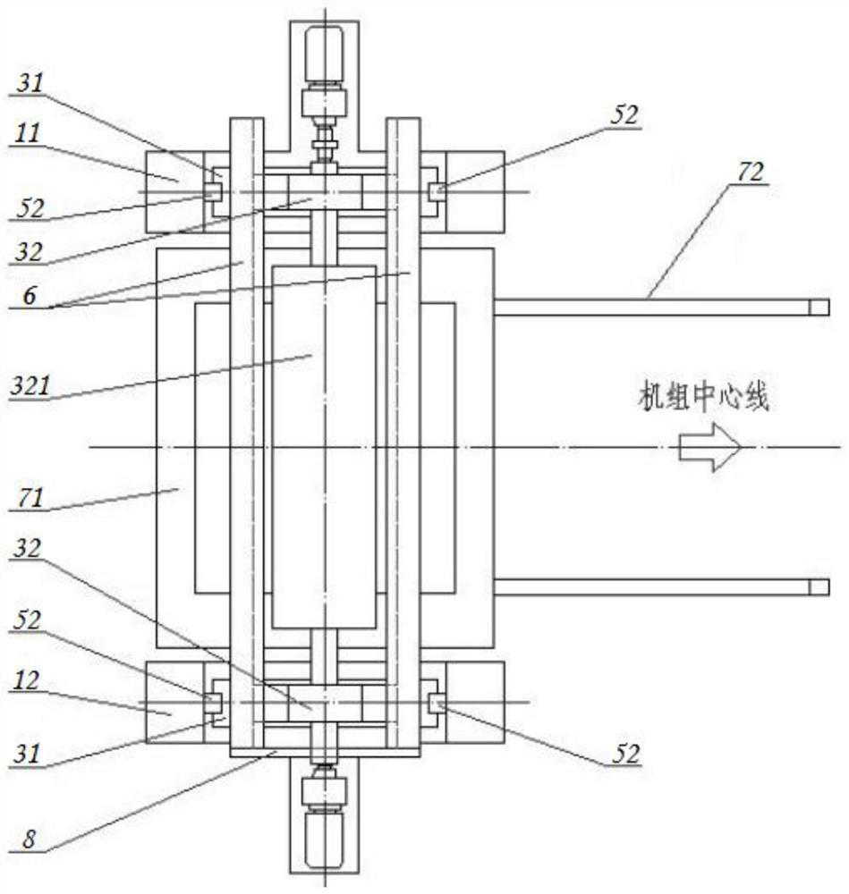
[0025] Such as Figure 1-Figure 3 , the embodiment of the present invention provides a single-roll coating machine, including a frame 1, an upper coating roller 22 and a lower coating roller 32, which further includes an upper roller frame 21, arranged on the top of the frame 1 and used to drive the The upper lifting mechanism 23 for lifting the upper roller frame 21, the lower roller frame 31, and the lower lifting mechanism 33 arranged at the bottom of the frame 1 and used to drive the lifting of the lower roller frame 31; the bea...


PUM


Abstract

The invention relates to a single-roller coating machine. The single-roller coating machine comprises a rack, an upper coating roller, a lower coating roller, an upper roller frame, an upper lifting mechanism, a lower roller frame and a lower lifting mechanism, wherein the rack is fixedly installed on a workshop platform, the section, perpendicular to the strip steel running direction, of the rackis in an n shape or a rectangular shape, a bearing seat of the upper coating roller and a bearing seat of the lower coating roller are arranged on the roller frames in a sliding manner correspondingly, the sliding direction is parallel to the axial direction of coating roller bodies, a transmission side frame body and / or an operation side frame body of the rack are / is provided with roller replacing channels allowing the upper coating roller and the lower coating roller to pass through. The rack is fixedly mounted on the workshop platform, and the n-shaped or rectangular section is adopted, sothat the structural rigidity and stability of the whole equipment are guaranteed, and the uniformity of a coating can be improved; and the upper coating roller and the lower coating roller are designed to be installed on the corresponding roller frames in a sliding mode, other components do not need to be moved in the roller replacing operation process, operation is convenient and fast, time andlabor are saved, maintenance efficiency can be remarkably improved, and maintenance cost is reduced.

Description

technical field [0001] The invention belongs to the technical field of metallurgical equipment, and in particular relates to a single-roll coating machine. Background technique [0002] At present, in the production of silicon steel, a single-roll coating machine is generally used to coat magnesium oxide coating liquid and a low-viscosity insulating layer coating liquid on silicon steel. The structure of the single-roll coating machine is basically spraying and extrusion, that is, There is a non-transmission coating roller on the upper and lower sides of the steel. These two coating rollers are grooved rollers. Excessive coating liquid is sprayed at the entrance of the upper coating roller, lower coating roller and strip steel. The film thickness of the coating is adjusted by the mutual pressing force between the roller and the lower coating roller. [0003] At present, the C-frame type single-roll coating machine is more widely used. The frame is a "C"-shaped frame and a m...

Claims


Application Information

Patent Timeline
IPC IPC(8): B05C1/08B05C11/10
CPCB05C1/08B05C11/1039
Inventor 艾晶陈洁况群意
Owner WISDRI ENG & RES INC LTD
Why Eureka
Try Eureka