Waste syringe recovery device with cleaning and syringe needle separating functions
A technology for recycling device and syringe, applied in the field of waste syringe recycling device, can solve the problems of time-consuming and laborious, injury to operators, low work efficiency, etc., and achieve the effects of improving cleaning effect, avoiding manual operation, and improving work efficiency
- Summary
- Abstract
- Description
- Claims
- Application Information
AI Technical Summary
Problems solved by technology
Method used
Image

Examples
Embodiment Construction
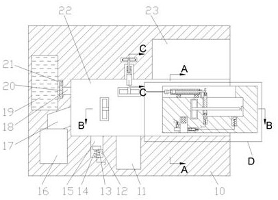
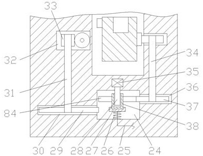
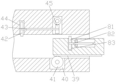
[0019] Combine below Figure 1-6 The present invention is described in detail, wherein, for the convenience of description, the orientations mentioned below are defined as follows: figure 1 The up, down, left, right, front and back directions of the projection relationship itself are the same.
[0020] A waste syringe recovery device with cleaning and needle separation functions described in conjunction with accompanying drawings 1-6, includes a main box body 10, and a working chamber 22 with an opening to the right is provided inside the main box body 10, and the working chamber The upper end wall of the chamber 22 is communicated with a placement chamber 23 with an opening to the right, the lower end wall of the working chamber 22 is communicated with a needle chamber 11, the left side of the working chamber 22 is provided with a clean water chamber 19, and the right end of the clean water chamber 19 is The wall is communicated with a water retaining plate chamber 21, and t...
PUM
 Abstract
Description
Claims
Application Information
PatSnap Eureka turns technology decisions into work you can execute. Powered by our Innovation Knowledge Graph, it runs expert workflows across engineering, life sciences, materials and intellectual property. Get your review-ready output in minutes.


