Wood cutting and polishing device for gardens

A technology for cutting and grinding wood, used in grinding drives, woodworking appliances, grinding machines, etc.

Inactive Publication Date: 2021-03-16
倪婷
View PDF0 Cites 5 Cited by
  • Summary
  • Abstract
  • Description
  • Claims
  • Application Information

AI Technical Summary

Problems solved by technology

[0004] The present invention provides a wood cutting and grinding device for gardens, which solves the problems in the above-mentioned background technology

Method used


Image

  • Wood cutting and polishing device for gardens
  • Wood cutting and polishing device for gardens
  • Wood cutting and polishing device for gardens

Examples


Embodiment 1

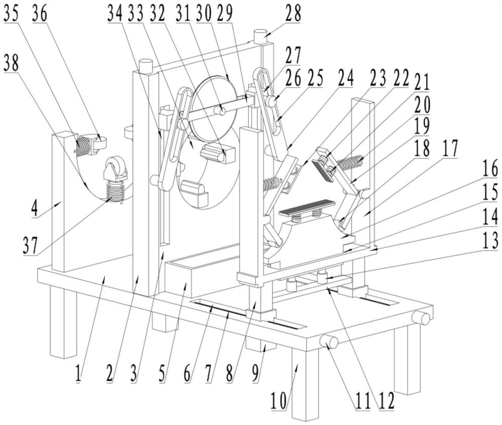
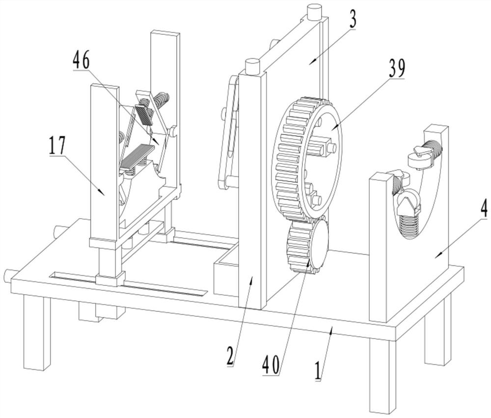
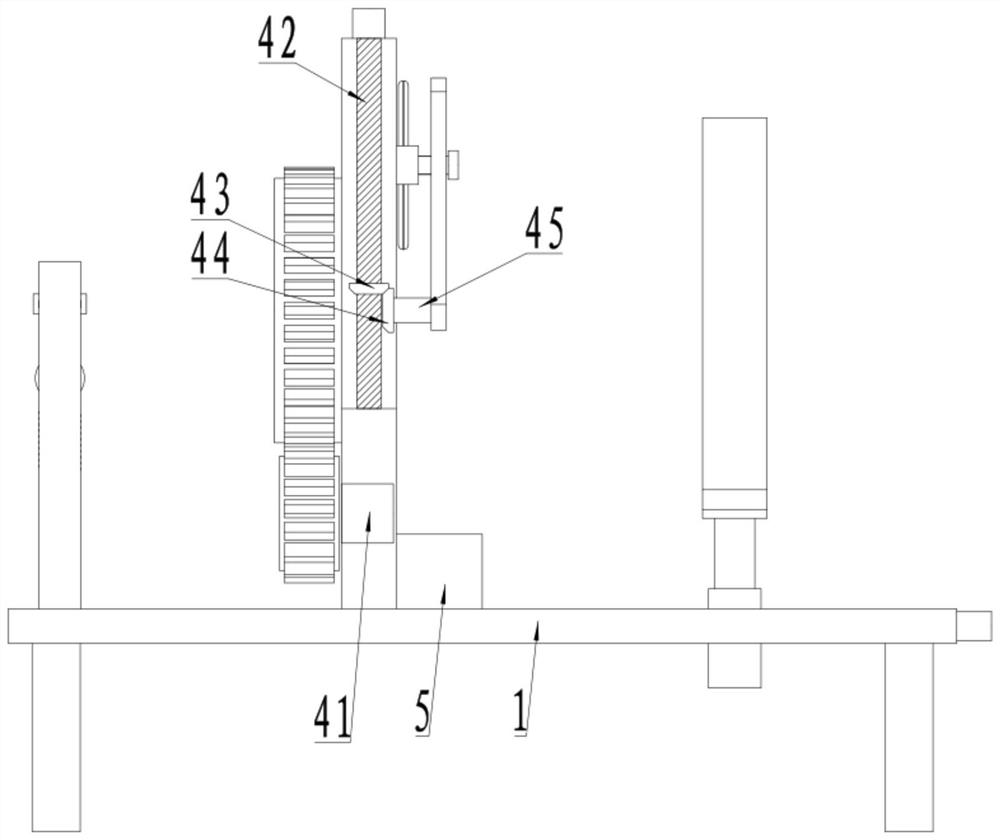
[0022] see Figure 1-4 , a wood cutting and polishing device for gardens, comprising a base plate 1, the four corners of the bottom of the base plate 1 are fixedly connected to support legs 10, the base plate 1 is fixedly connected to a first mounting plate 3, and the first mounting plate 3 is provided with an installation port 33 The first mounting plate 3 on one side of the installation port 33 is rotationally connected to the mounting gear ring 39, and the side wall of the first mounting plate 3 below the mounting gear ring 39 is rotationally connected to the drive gear 40, and the shaft of the drive gear 40 is on one side of the axial direction. The first mounting plate 3 is fixedly connected to the first motor 41, the output shaft of the first motor 41 is fixedly connected to the rotating shaft of the drive gear 40, and the drive gear 40 is meshed with the installation gear ring 39 for transmission connection. The polishing device 32 is provided, and the polishing device ...

Embodiment 2

[0029] see Figure 1-4 The other content of this embodiment is the same as that of Embodiment 1, except that: the bottom of the first mounting plate 3 below the cutting disc 30 is fixedly connected to the receiving groove 5 .

[0030] During the implementation of the present invention, wood is manually placed on the supporting rollers 36 on the second mounting plate 4, and under the action of the supporting rollers 36, the wood is slid forward and passed through the mounting opening 33 on the first mounting plate 3, Extend between the clamping plates 23 between the coaming plates 2, start the hydraulic telescopic column 13 to drive the support block 16 to move upward, and the arc of the rotating wheel 18 on the first rotating plate 46 on both sides of the support block 16 on the support block 16 The first rotating plate 46 rotates to drive the second rotating plate 19 to rotate. Under the action of the clamping plate 23, the clamping and fixing operation of the wood is realize...


PUM


Abstract

The invention discloses a wood cutting and polishing device for gardens, and relates to the technical field of wood processing equipment for gardens. The wood cutting and polishing device for gardenscomprises a bottom plate, supporting legs are fixedly connected to four corners of the bottom of the bottom plate, a first mounting plate is fixedly connected to the bottom plate, a mounting opening is formed in the first mounting plate, a mounting gear ring is rotatably connected to the position, on one side of the mounting opening, of the first mounting plate, a driving gear is rotationally connected to the position, below the mounting gear ring, of the side wall of the first mounting plate, polishing devices are arranged in the mounting gear ring, the polishing devices are arranged on the mounting gear ring at equal radian intervals, a sliding groove is formed in the first mounting plate and on the side, away from the mounting gear ring, of the mounting opening, mounting blocks are slidably connected into the sliding groove, a mounting frame is fixedly connected between the mounting blocks, the mounting frame is of a cavity structure with two through sides, and a cutting disc is rotationally connected into the mounting frame. The device is reasonable in structural principle design and strong in practicability.

Description

technical field [0001] The invention relates to the technical field of garden wood processing equipment, in particular to a garden wood cutting and polishing device. Background technique [0002] Wood is the lignified tissue of plants capable of secondary growth, such as trees and shrubs. After the primary growth of these plants ends, the vascular cambium in the rhizome becomes active, developing bast outward and wood inward. Wood is the general term for plant tissues that develop inwardly from the vascular cambium, including xylem and parenchyma rays. Wood plays a great supporting role in human life. According to the different properties and characteristics of wood, people use them in different ways. [0003] Before the wood is put into real use, a series of processing operations are required. The most basic processing operation is to cut the shaped wood into sections for easy transportation, and at the same time polish the skin, and then process it. The traditional wood...

Claims


Application Information

Patent Timeline
IPC IPC(8): B24B19/24B24B47/12B24B41/02B24B41/06B24B41/00B27C5/00
CPCB24B19/24B24B41/005B24B41/02B24B41/06B24B47/12B27C5/00
Inventor 倪婷
Owner 倪婷
Why Eureka
Try Eureka