Novel suspension polishing device
A kind of equipment and a new technology, applied in the field of new suspension polishing equipment, can solve the problems that affect the polishing pass rate, unstable product polishing quality, easy to collide with each other, etc., so as to ensure the stability and quality of polishing, improve the efficiency and quality of polishing, and prevent The effect of collision damage
- Summary
- Abstract
- Description
- Claims
- Application Information
AI Technical Summary
Problems solved by technology
Method used
Image

Examples
Embodiment 1
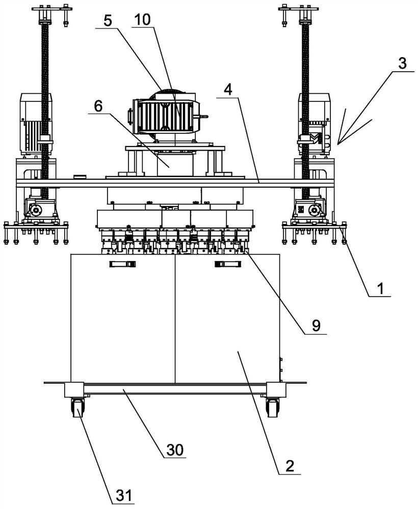
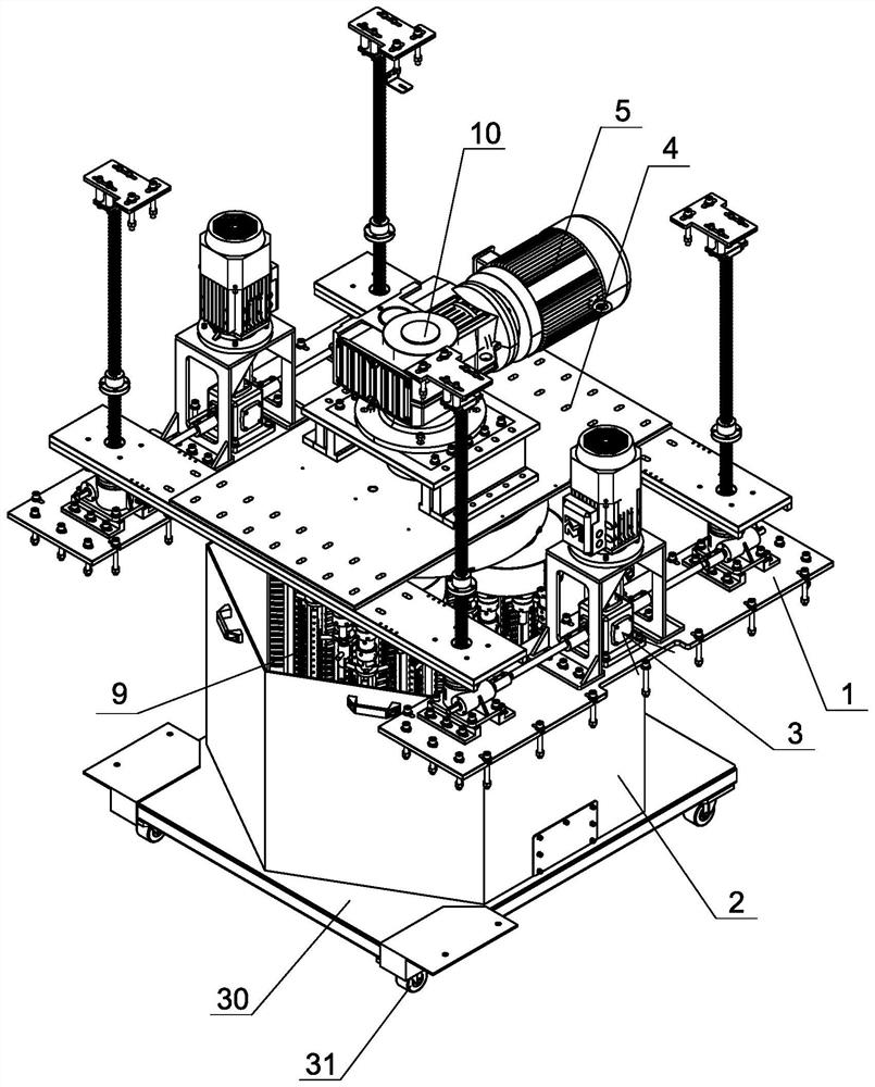
[0034] Embodiment one: see Figure 1-5 As shown, a novel suspension polishing equipment includes a frame 1, a polishing bin 2 arranged on the frame, and a polishing mechanism, and the polishing mechanism is moved and arranged above the polishing bin through a drive mechanism 3. The polishing mechanism is installed on a bracket 4, and the two ends of the bracket are connected with the driving mechanism, and the driving mechanism drives the bracket to move up and down;
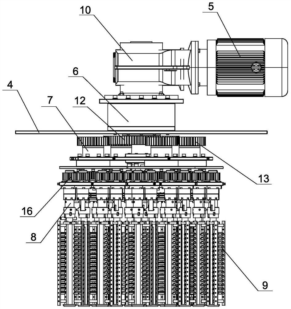
[0035] The polishing mechanism comprises a main shaft drive motor 5, a driving main shaft 6, multiple sets of secondary transmission main shafts 7, multiple sets of tertiary connecting main shafts 8 and multiple sets of product positioning jigs 9, the top of each group of said product positioning jigs is connected to a Group the bottom detachable connection of the tertiary connection spindle;
[0036] The top of the drive spindle is connected to the support for rotation, the spindle drive motor is installed on ...
Embodiment 2
[0051] Embodiment two: see Figure 6 As shown, a new type of suspension polishing equipment, in this embodiment, its structure is basically similar to Embodiment 1, the difference is that: the bottom of the polishing bin is installed on a support plate 30, the bottom of the support plate Rotately connected with the frame through a rotating shaft 32, a rotating motor 33 is provided on the frame below the supporting plate, a bottom gear 34 is provided at the bottom of the rotating shaft, and a side portion is provided on the output shaft of the rotating motor. Gear 35, said side gear having a smaller diameter than said bottom gear, said side gear meshing with said bottom gear. The rotation direction of the rotating shaft is opposite to the rotation direction of the driving spindle, so that the relative speed between the product positioning fixture and the polishing bin is faster, that is, the relative speed between the product and the abrasive is faster, and the polishing effici...
Embodiment 3
[0052] Embodiment three: see Figure 7 As shown, a new type of suspension polishing equipment, in this embodiment, its structure is basically similar to that of Embodiment 1, the difference is that: the secondary gear is connected with the main gear through a connection mechanism, and the connection mechanism includes a connection Gear 36, the two sides of the connecting gear mesh with the secondary gear and the main gear respectively.
[0053] In this embodiment, in order to increase the distance between the two-stage transmission spindle and the drive spindle, that is, the distance between the three-stage connection spindle on the adjacent two-stage transmission spindle, in order to reduce the rotation between adjacent product positioning fixtures When grinding, the abrasive on the side is stirred to other positions to affect the polishing quality. Using the connecting gear to mesh the secondary gear with the main gear can not only increase the distance between the two, but ...
PUM
 Abstract
Description
Claims
Application Information
 - R&D Engineer
- R&D Manager
- IP Professional
- Industry Leading Data Capabilities
- Powerful AI technology
- Patent DNA Extraction
Browse by: Latest US Patents, China's latest patents, Technical Efficacy Thesaurus, Application Domain, Technology Topic.
© 2024 PatSnap. All rights reserved.Legal|Privacy policy|Modern Slavery Act Transparency Statement|Sitemap