
Quick-drying color printing machine with anti-contamination structure

A printing machine and anti-contamination technology, which is applied in the direction of printing presses, rotary printing machines, screen printing machines, etc., can solve the problems of different widths, cardboard tilting, cardboard ink staining, etc., to avoid contamination and ensure The effect of normal transmission

Inactive Publication Date: 2021-03-16
马鞍山聚儒信息科技有限公司
View PDF1 Cites 0 Cited by
  • Summary
  • Abstract
  • Description
  • Claims
  • Application Information

AI Technical Summary

Problems solved by technology

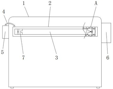
[0006] The purpose of the present invention is to provide a quick-drying color printing machine with an anti-contamination structure, to solve the existing color printing machine on the market proposed by the above-mentioned background technology, when the printed cardboard is removed, the colored ink In order to fully dry, when stacking multiple printing cardboards, it is easy to cause ink stains between the cardboards, affecting the printing quality of the cardboards. At the same time, when printing cardboards of different sizes, due to the different widths of the cardboards, the When the cardboard is moved out, it is not conducive to the smooth passage of the cardboard, and it is easy to cause the cardboard to tilt and the contamination of the printing area and the outlet

Method used


Image

  • Quick-drying color printing machine with anti-contamination structure
  • Quick-drying color printing machine with anti-contamination structure
  • Quick-drying color printing machine with anti-contamination structure

Examples


Embodiment Construction

[0028] Based on the embodiments of the present invention, all other embodiments obtained by persons of ordinary skill in the art without making creative efforts belong to the protection scope of the present invention.

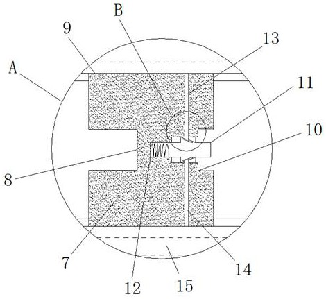
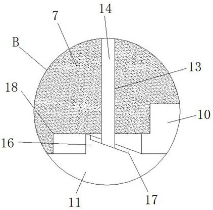
[0029] see Figure 1-7 , the present invention provides a technical solution: a quick-drying color printing machine with an anti-contamination structure, including a printing machine body 1, a quick-drying mechanism 2, a plate outlet 3, a connecting pipe 4, a hot air blower 5, and a paint box 6. Limiting structure 7, limiting groove 8, sliding groove 9, extrusion port 10, adjusting rod 11, sliding port 12, sliding hole 13, limiting rod 14, connecting cavity 15, pushing part 16, fitting groove 17 , limit port 18, connector 19, blowing port 20, receiving part 21, limit tooth groove 22 and pinch part 23, the front side of printing machine body 1 is fixed with quick-drying mechanism 2, and the middle part of quick-drying mechanism 2 There is a plate outlet 3 throu...


PUM


Abstract

The invention discloses a quick-drying color printing machine with an anti-contamination structure. The machine comprises a printing machine body, a quick-drying mechanism, a connecting pipe and limiting structures, the quick-drying mechanism is fixed to the front side of the printing machine body, and a plate outlet allowing a printing plate to pass through is formed in the middle of the quick-drying mechanism in a penetrating mode. An annular communicating cavity is formed in the middle of a shell of the quick-drying mechanism and is communicated with an air blowing opening in the inner wallof the plate outlet, and the two limiting structures capable of being adjusted in a sliding mode are arranged in the plate outlet. According to the printing machine, a corresponding drying mechanismis arranged at the position discharging paper plates of the color printing machine, the upper faces and the lower faces of the paper plates can be directly dried in the paper plate moving-out process,the contamination problem of the paper plates in the subsequent stacking process is avoided, meanwhile, by arranging the adjustable limiting structures at the outlet discharging the paper plates, thepaper plates with different widths can be adjusted, and stable moving-out of the paper plates is facilitated.

Description

technical field [0001] The invention relates to the technical field of color printing machines, in particular to a quick-drying color printing machine with an anti-contamination structure. Background technique [0002] A color printing machine mainly uses inkjet to print text or patterns on paper or cardboard that needs to be printed, for example, a color printing machine that facilitates ink replacement and can filter toner for comparison with application number CN201821522600.4 and authorization announcement date 20190510, including The body, the first filter screen and the suction pipe, the left side of the body is provided with a mounting groove, and the inner side of the mounting groove is installed with a spring, the right side of the spring is fixed with a limit plate, and between the limit plate and the spring For welding, the inside of the installation groove is provided with an ink cartridge, and the top of the ink cartridge is fixed with a bump, the inside of the ...

Claims


Application Information

Patent Timeline
IPC IPC(8): B41F17/00B41F22/00B41F23/04
CPCB41F17/00B41F22/00B41F23/04
Inventor 胡秀凤
Owner 马鞍山聚儒信息科技有限公司
Learn More