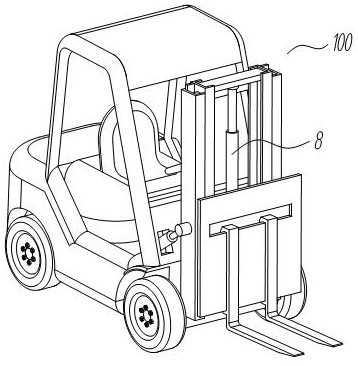
Hydraulic system for forklift lifting oil cylinder
A hydraulic system and oil cylinder technology, which is applied in the field of forklift lifting cylinder hydraulic system, can solve problems such as failure to work, damage of the first two-position two-way solenoid valve, second two-position two-way solenoid 5, etc., so as to save energy and realize energy recovery , the effect of ensuring safety
- Summary
- Abstract
- Description
- Claims
- Application Information
AI Technical Summary
Problems solved by technology
Method used
Image

Examples
Embodiment 1
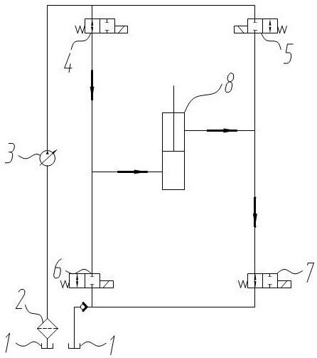
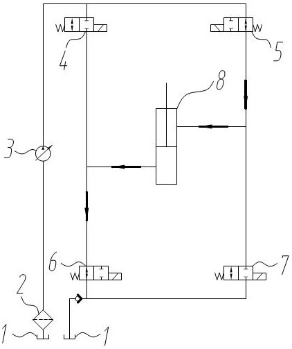
[0030] The oil outlets of the third electromagnetic valve 6 and the fourth electromagnetic valve 7 and the oil inlet of the fifth electromagnetic valve 9, the oil outlet of the fifth electromagnetic valve 9 are connected to the oil tank 1, and the first oil circuit 101 Cartridge valve 2 14 and seventh solenoid valve 15 are sequentially connected with the rod cavity of lift cylinder 8, and the three-position four-way solenoid valve 2 is connected between the first oil circuit 101 and the rodless cavity of lift cylinder 8. 13. A three-position four-way solenoid valve 10 is connected between the second oil circuit 102 and the rod cavity of the lift cylinder 8, and a three-position four-way solenoid valve 10 is connected between the second oil circuit 102 and the rodless cavity 1 of the lift cylinder 8 in sequence. Cartridge valve one 11, sixth solenoid valve 12, oil port one A1 of the three-position four-way solenoid valve two 13 is connected to the first oil circuit 101, oil port...
Embodiment 2
[0033] On the basis of the first improved embodiment above, this embodiment is improved as follows, the oil port three C1 and the oil port three C2 are connected to the oil port one A3 of the flow regulating valve 16, the oil port three C1 and the oil port three C2 Oil port three C2 is also connected to one port of the three-position two-way solenoid valve 17, the other port of the three-position two-way solenoid valve 17 is connected to the accumulator two 26, and the oil port two B3 of the flow regulating valve 16 is connected to the oil tank 1. Oil port three C3 is connected to the first relief valve 18 and oil port one A4 of the two-position four-way solenoid valve 19, the first relief valve 18 is connected to the oil tank 1, and the oil of the two-position four-way solenoid valve 19 Port two B4 is connected to the first chamber 20.1 of the supercharger 20, the oil port three C4 of the two-position two-way solenoid valve 19 is connected to the fuel tank 1, and the oil port ...
PUM
 Abstract
Description
Claims
Application Information