Orthotropic steel bridge deck fatigue crack detection equipment and use method thereof

A technology for steel bridge decks and fatigue cracks, applied in measuring devices, using sound waves/ultrasonic waves/infrasonic waves to analyze solids, using sound waves/ultrasonic waves/infrasonic waves for material analysis, etc., can solve problems affecting ultrasonic detection accuracy, small manipulation space, and detection efficiency low level problem

Active Publication Date: 2021-03-16
SOUTHWEST JIAOTONG UNIV +1
View PDF22 Cites 4 Cited by
  • Summary
  • Abstract
  • Description
  • Claims
  • Application Information

AI Technical Summary

Problems solved by technology

In practical application, due to various factors such as the environment of the structure, load changes, and production technology, fatigue cracks often occur on orthotropic steel bridge decks. After large fatigue cracks appear, traffic needs to be interrupted for maintenance and reinforcement, which is harmful to the society. cause greater impact
At present, the fatigue crack detection of existing orthotropic steel deck bridges is mainly carried out manually in the steel box girder. The detection efficiency is low, the manipulation space is small, and the fatigue cracks cannot be detected comprehensively and timely.
[0003] Existing orthotropic bridge deck testing equipment mainly uses a crawler-type magnetic wheel mechanism as the walking system, for example, the invention patent with the publication number of CN106950286B discloses a self-propelled trolley for ultrasonic testing of weld seams on the top plate of steel bridge decks; The invention patent No. CN111021244A discloses an intelligent orthotropic steel bridge deck fatigue crack detection robot, and for example, the invention patent with the publication number CN109613010A discloses an orthotropic steel bridge deck fatigue crack detection system, but the above-mentioned system While walking, the ultrasonic probe is used for detection, but the track wheel will vibrate the steel structure to a certain extent, which will affect the accuracy of ultrasonic detection; another way is to use a smooth permanent magnet wheel, such as the invention patent with the publication number CN110824011B, published A device for fatigue crack detection of orthotropic deck is developed. The ultrasonic probe carried by the device is used to inspect the fatigue crack of orthotropic steel bridge deck, but the device can only detect one U-rib of the orthotropic deck. The weld seam on one side of the groove cannot realize automatic lateral movement, and the existing inspection equipment cannot start from the end of a steel box girder to the end of the other side

Method used


Image

  • Orthotropic steel bridge deck fatigue crack detection equipment and use method thereof
  • Orthotropic steel bridge deck fatigue crack detection equipment and use method thereof
  • Orthotropic steel bridge deck fatigue crack detection equipment and use method thereof

Examples


Embodiment 1

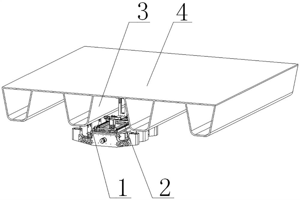
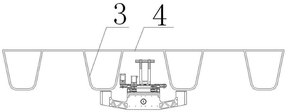
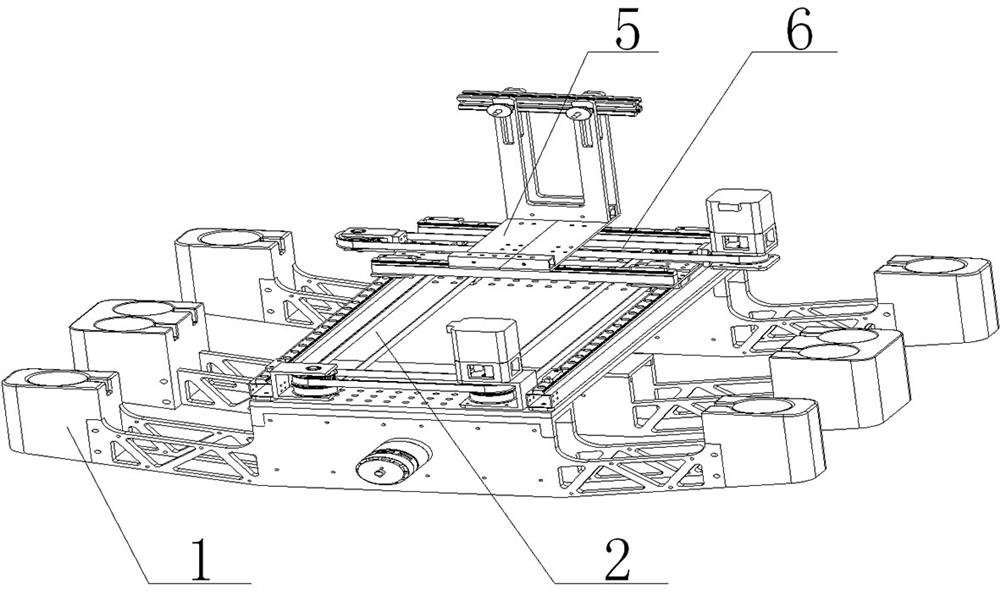
[0056] Such as Figures 1 to 14 As shown, the present invention is an orthogonal opposite steel bridge panel fatigue crack detection equipment, including walking assembly 1 and a detection platform assembly 2, the walking assembly 1 including an active travel mechanism 45, a passive travel mechanism 49, and a third drive mechanism 44. The active traveling mechanism 45 and the passive travel mechanism 49 are both a curved structure, and the active travel mechanism 45 and the top of the passive travel mechanism 49 are provided with an electromagnet 46, and the transmission shaft 48 of the third drive mechanism 44 runs through passive. After the traveling mechanism 49 is threaded with the active traveling mechanism 45, when the third drive mechanism 44 is rotated by the drive shaft 48, the active traveling mechanism 45 can be close or away from the passive travel mechanism 49;

[0057] The detection platform assembly 2 includes a first support plate 14, a track square pipe 12, a first...

Embodiment 2

[0061] Based on the first embodiment, the passive travel mechanism 49 is two, and the active travel mechanism 45 is located between the two passive travel mechanisms 49; the active travel mechanism 45 and the passive travel mechanism 49 each include a fixed plate 52, two The connecting arm 50 and the two fixing heads 51 are both a hollow structure, and the two connecting arm 50 are connected to both sides of the fixing plate 52, and the other end is connected to the fixed head 51, the overall arc Structure, the electromagnet 46 is located at the top of the fixed head 51, and the first support plate 14 of the detecting platform assembly 2 is located at the top of each fixing plate 52; the third drive mechanism 44 is located in one of the passive walking mechanisms 49. On the sidewall, the drive shaft 48 of the third drive mechanism 44 sequentially penetrates the retention plate 52 of the active travel mechanism 45 and the passive travel mechanism 49, and the fixing plate 52 of the ...

Embodiment 3

[0063] On the basis of Example 2, the top portion of the rail square tube 12 is also provided with a first slide rail 42, and a first slider 16 having a match thereof, a first slider 16 It is possible to slide in the first sliding rail 42 in the first slide 42, and the top of the first slider 16 is connected to the bottom of the second support plate 17.


PUM


Abstract

The invention discloses orthotropic steel bridge deck fatigue crack detection equipment which comprises a walking assembly and a detection platform assembly, the walking assembly comprises a driving walking mechanism, a driven walking mechanism and a third driving mechanism, and the driving walking mechanism and the driven walking mechanism are each of an arc-shaped structure; electromagnets are arranged at the tops of the two ends of the driving walking mechanism and the driven walking mechanism, a transmission shaft of the third driving mechanism penetrates through the driven walking mechanism and then is in threaded connection with the driving walking mechanism, and when the third driving mechanism drives the transmission shaft to rotate, the driving walking mechanism can get close to or get away from the driven walking mechanism. The orthotropic plate fatigue crack is automatically detected by carrying a phased array ultrasonic detector, meanwhile, in the moving process of the orthotropic plate fatigue crack on the orthotropic steel bridge deck, the vibration of the equipment can be reduced, and the detection accuracy is improved.

Description

Technical field [0001] The present invention relates to the field of orthogonal anisotropic steel bridge panel fatigue crack detection, and more particularly to a fatigue crack detection equipment for orthogonal opposite steel bridge panels. Background technique [0002] The orthogonal heterogeneous steel bridge panel has highlights of light, high carrying capacity, and wide applicability, and wide application in bridge engineering. Since the rigidity of the structure is different in the longitudinal direction of the bridge and the lateral direction of the laterally perpendicular direction, the structure is anisotropy. In practical applications, under the practical application, the environment, load changes, and production process, the exactlyorous steel bridge panel often produces fatigue cracking, after growing fatigue crack, need to interrupt traffic to repair and reinforce, for society Resulting in a big impact. At present, the fatigue crack detection of existing orthodoxic s...

Claims


Application Information

Patent Timeline
Patent Type & Authority Applications(China)
IPC IPC(8): G01N29/04G01N29/265E01D19/10B62D57/02
CPCB62D57/02E01D19/106G01N29/04G01N29/265
Inventor 勾红叶韩冰王君明华辉蒲黔辉赵天祺钟子城李金耀
Owner SOUTHWEST JIAOTONG UNIV
Why Eureka
Try Eureka