
Forward modeling method and device based on finite difference of primary scattered wave equation

A forward simulation and finite difference technology, applied in the field of geophysical exploration, can solve the problem of low accuracy in the identification of small-scale non-uniform mass wavefield features

Active Publication Date: 2021-03-16
CHINA UNIV OF PETROLEUM (EAST CHINA)
View PDF4 Cites 0 Cited by
  • Summary
  • Abstract
  • Description
  • Claims
  • Application Information

AI Technical Summary

Problems solved by technology

[0003] The purpose of the embodiment of the present invention is to provide a forward modeling method and device based on the finite difference of the first-order scattered wave equation, to solve the problem of identification accuracy of the existing scattered wave numerical simulation for the wave field characteristics of small-scale inhomogeneous bodies not high problem

Method used


Image

  • Forward modeling method and device based on finite difference of primary scattered wave equation
  • Forward modeling method and device based on finite difference of primary scattered wave equation
  • Forward modeling method and device based on finite difference of primary scattered wave equation

Examples


Embodiment Construction

[0045] The specific implementation manners of the embodiments of the present invention will be described in detail below in conjunction with the accompanying drawings. It should be understood that the specific implementation manners described here are only used to illustrate and explain the implementation manners of the present invention, and are not intended to limit the implementation manners of the present invention.

[0046] It should be noted that if there are directional indications (such as up, down, left, right, front, back...) in the implementation of the present application, the directional indications are only used to explain the position in a certain posture (as shown in the accompanying drawings). If the specific posture changes, the directional indication will also change accordingly.

[0047] In addition, if there are descriptions involving "first", "second", etc. in the embodiments of the present application, the descriptions of "first", "second" and so on are ...


PUM


Abstract

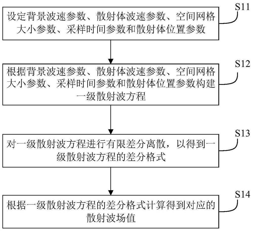
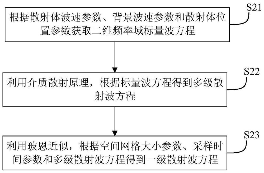
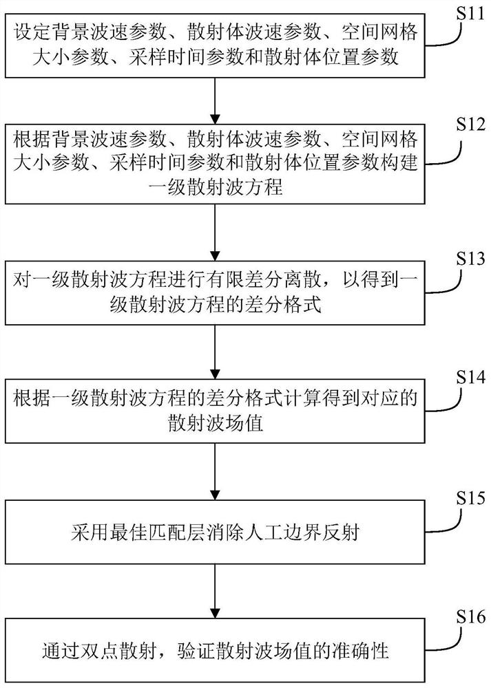
The invention discloses a forward modeling method and device based on a finite difference of a primary scattered wave equation. The method comprises the following steps: setting a background wave velocity parameter, a scatterer wave velocity parameter, a space grid size parameter, a sampling time parameter and a scatterer position parameter; constructing a primary scattered wave equation accordingto the background wave velocity parameter, the scatterer wave velocity parameter, the space grid size parameter, the sampling time parameter and the scatterer position parameter; carrying out finitedifference discretization on the primary scattered wave equation to obtain a difference format of the primary scattered wave equation; and calculating to obtain a corresponding scattered wave field value according to the difference format of the primary scattered wave equation. According to the invention, primary scattered waves are separated from the complex wave field so that the identificationof scattered wave numerical simulation on the characteristics of a small-scale non-uniform plastid wave field is clearer and finer.

Description

technical field [0001] The invention relates to the technical field of geophysical exploration, in particular to a forward modeling method and device based on the finite difference of the first-order scattered wave equation. Background technique [0002] With the continuous development of seismic exploration technology, reflection wave exploration technology has been widely used and achieved good results in large-scale structures, but it is proposed based on the horizontal layered model. When there are special geological bodies such as pinch-outs, lenses, and caves, or when there are lateral changes in lithology, the reflected wave signal received by the ground is weak and the signal-to-noise ratio is low, which poses a huge challenge to the reflected wave method. For example, the carbonate reservoirs in western my country are mainly fracture-voids (cavities) with strong heterogeneity, and the scattered wave method is more universal for such reservoirs. When the source is e...

Claims


Application Information

Patent Timeline
IPC IPC(8): G01V1/30
CPCG01V1/282G01V1/30G01V2210/66
Inventor 吴国忱张博印兴耀宗兆云曹丹平张佳佳
Owner CHINA UNIV OF PETROLEUM (EAST CHINA)
Learn More