In-throat emetic head and emetic device with emetic head for emergency internal medicine
An emetic and inner tube technology, which is applied in the field of medical devices, can solve the problems of inconvenient cleaning, vomit with germs, and incomplete cleaning of the device, and achieve the effect of easy storage and cleaning
- Summary
- Abstract
- Description
- Claims
- Application Information
AI Technical Summary
Problems solved by technology
Method used
Image
Examples
Embodiment 1
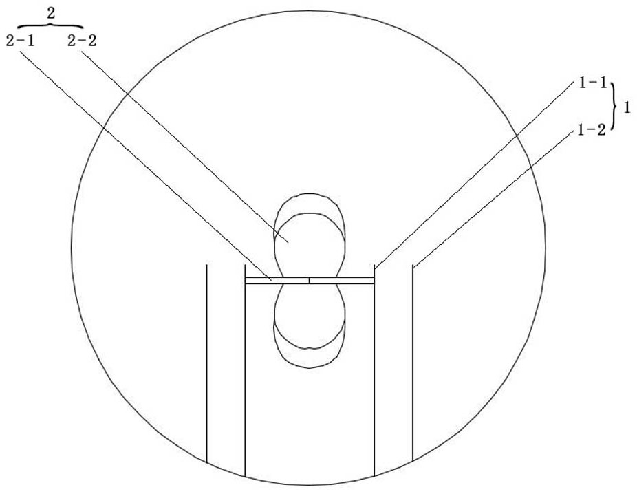
[0037] Such as figure 1 Shown: a throat-entry emetic head, including a throat-entry tube 1 and a stimulating contact assembly 2 . The inlet pipe 1 includes an inner pipe 1-1 and an outer pipe 1-2, and there is an annular gap between the inner pipe 1-1 and the outer pipe 1-2. The stimulating contact assembly 2 includes a rotating shaft 2-1 and a contact 2-2. The contact 2-2 includes a blade 2-3 and a stimulating part arranged on the outer edge of the blade 2-3. The rotating shaft 2-1 is installed at the head end of the inlet pipe 1, and the two ends of the rotating shaft 2-1 respectively pass through the side wall of the inner pipe 1-1 and are placed in the annular gap between the inner pipe 1-1 and the outer pipe 1-2 . The blade 2-3 of the contact 2-2 is sleeved on the rotating shaft 2-1 in the inner tube 1-1. The contact 2-2 includes a blade 2-3 and a rubber layer wrapped around the outer edge of the blade 2-3.
[0038] Under the effect of negative pressure suction, the ...
Embodiment 2
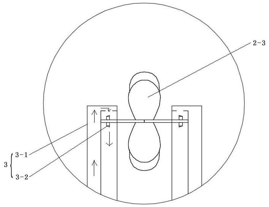
[0041] Such as figure 2 and 4 Shown: a throat-entry emetic head, including a throat-entry tube 1 and a stimulating contact assembly 2 . The inlet pipe 1 includes an inner pipe 1-1 and an outer pipe 1-2, and there is an annular gap between the inner pipe 1-1 and the outer pipe 1-2. The stimulating contact assembly 2 includes a rotating shaft 2-1 and a contact 2-2. The contact 2-2 includes a blade 2-3 and a stimulating part arranged on the outer edge of the blade 2-3. The rotating shaft 2-1 is installed at the head end of the inlet pipe 1, and the two ends of the rotating shaft 2-1 respectively pass through the side wall of the inner pipe 1-1 and are placed in the annular gap between the inner pipe 1-1 and the outer pipe 1-2 . The blade 2-3 of the contact 2-2 is sleeved on the rotating shaft 2-1 in the inner tube 1-1. The contact 2-2 includes a blade 2-3 and a rubber layer wrapped around the outer edge of the blade 2-3.
[0042] The throat emetic head also includes an aux...
Embodiment 3
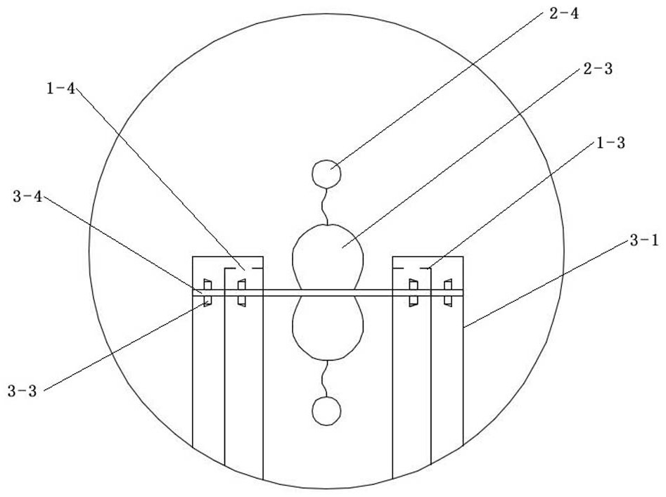
[0046] Such as image 3 Shown: a throat-entry emetic head, including a throat-entry tube 1 and a stimulating contact assembly 2 . The inlet pipe 1 includes an inner pipe 1-1 and an outer pipe 1-2, and there is an annular gap between the inner pipe 1-1 and the outer pipe 1-2. The stimulating contact assembly 2 includes a rotating shaft 2-1 and a contact 2-2. The contact 2-2 includes a blade 2-3 and a stimulating part arranged on the outer edge of the blade 2-3. The rotating shaft 2-1 is installed at the head end of the inlet pipe 1, and the two ends of the rotating shaft 2-1 respectively pass through the side wall of the inner pipe 1-1 and are placed in the annular gap between the inner pipe 1-1 and the outer pipe 1-2 . The blade 2-3 of the contact 2-2 is sleeved on the rotating shaft 2-1 in the inner tube 1-1. The contact 2-2 includes a blade 2-3 and a plurality of stimulating balls 2-4, and the plurality of stimulating balls 2-4 are connected to the edge of the head end o...
PUM
 Abstract
Description
Claims
Application Information
 - R&D
- Intellectual Property
- Life Sciences
- Materials
- Tech Scout
- Unparalleled Data Quality
- Higher Quality Content
- 60% Fewer Hallucinations
Browse by: Latest US Patents, China's latest patents, Technical Efficacy Thesaurus, Application Domain, Technology Topic, Popular Technical Reports.
© 2025 PatSnap. All rights reserved.Legal|Privacy policy|Modern Slavery Act Transparency Statement|Sitemap|About US| Contact US: help@patsnap.com


