Reverse fine cutting die and method for automotive specular metal decorating part

A technology for metal decoration and decorative parts, applied in metal processing equipment, feeding devices, manufacturing tools, etc., can solve problems such as the cracking of the cutter edge and the core of the lower mold, affecting the mass production rate of the product, and the optical change of the product surface, etc., to achieve improvement Long service life, improve product appearance quality, reasonable design effect

Pending Publication Date: 2021-03-19
FUZHOU FUYAO MOLD TECH
View PDF0 Cites 0 Cited by
  • Summary
  • Abstract
  • Description
  • Claims
  • Application Information

AI Technical Summary

Problems solved by technology

[0002] The cross-section of high-gloss metal decorative parts for vehicles is arched. At present, the fine-cutting molds for the end of high-gloss metal decorative parts for vehicles adopt the structure of punching the end from top to bottom. Fixed crushing, the lower mold core and the cutter are used as the knife edge, and then the cutter is driven to punch the end of the product from top to bottom, so as to achieve the effect of precise cutting of the end of the product; because the height of the side wall of the product cannot be guaranteed to be achieved during the actual mold adjustment process Due to the size of the digital model, the lower mold core needs to be avoided on both sides of the product end. The avoidance here will cause burrs on both sides of the product end during the punching process and optical changes on the product surface, and mold debugging personnel need to do more. Wheel repairs can solve product appearance problems. The structure of the lower mold core supporting the product is weak, which will easily lead to the cracking of the cutter edge and the lower mold core, resulting in product line interruption during the production process and affecting the mass production rate of the product.

Method used


Image

  • Reverse fine cutting die and method for automotive specular metal decorating part
  • Reverse fine cutting die and method for automotive specular metal decorating part
  • Reverse fine cutting die and method for automotive specular metal decorating part

Examples


Embodiment Construction

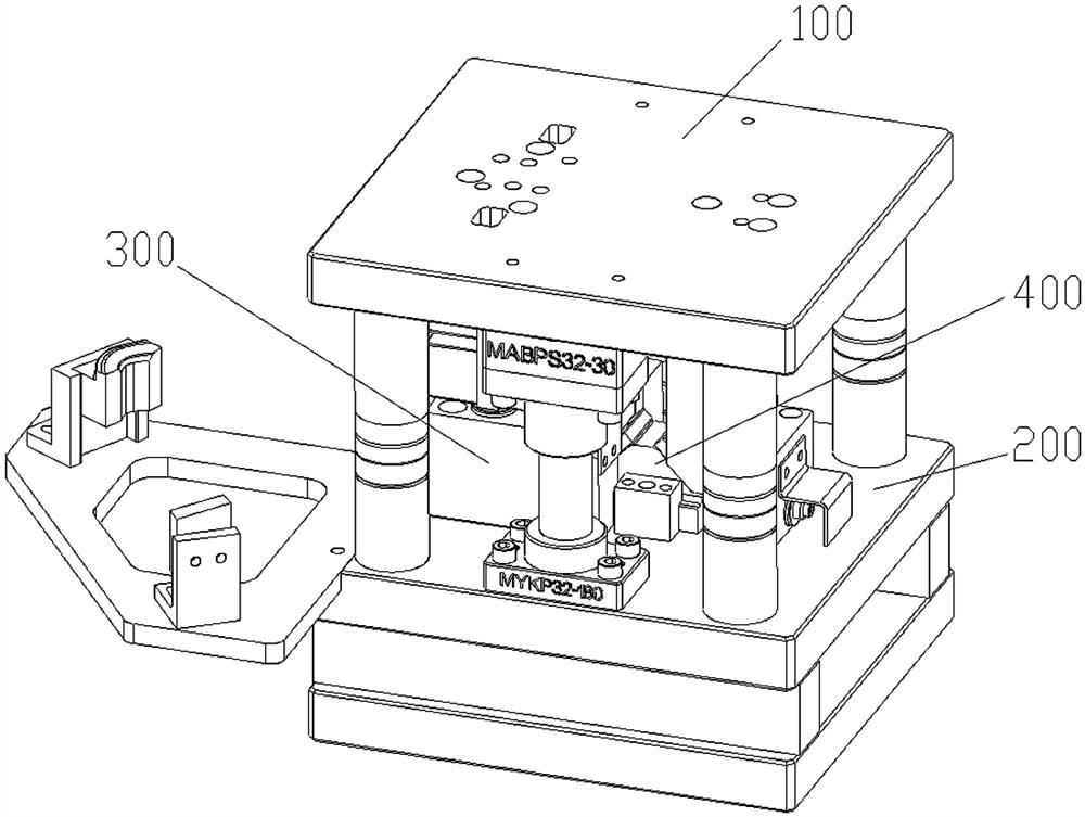
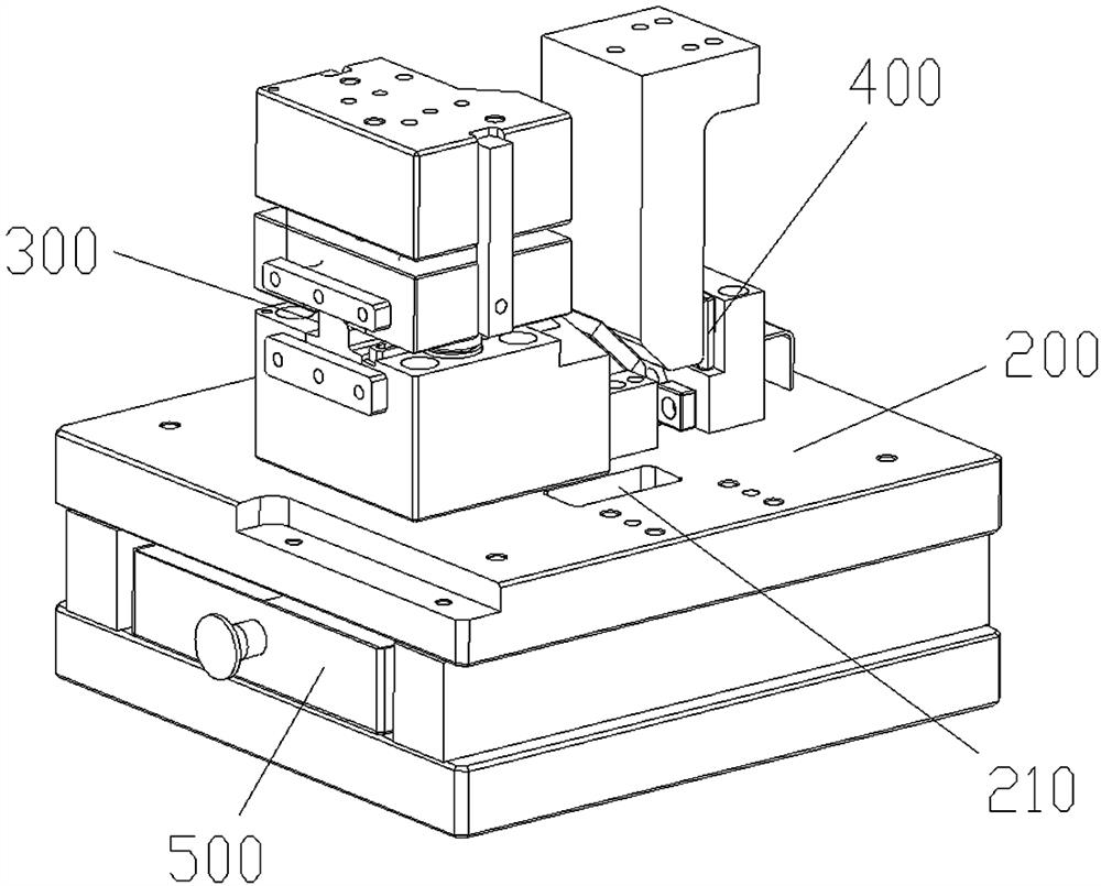
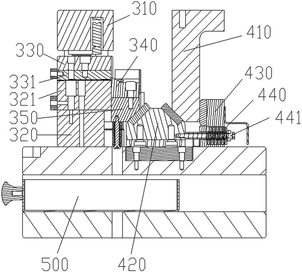
[0022] like Figure 1~6 As shown, a reverse fine-cutting mold for high-gloss metal decorative parts for vehicles includes an upper mold base 100, a lower mold base 200, a pressing material positioning mechanism 300, and a reverse wedge mechanism 400 located behind the pressing material positioning mechanism. The binder positioning mechanism 300 includes an upper mold holder 310 fixed on the lower side of the upper mold holder and a lower mold holder 320 fixedly installed on the lower mold holder. The mold core 321, the lower side of the upper mold fixing seat 310 is equipped with a binder seat 330, the lower side of the binder seat 330 is installed with a binder plate 331 for pressing the decorative parts, the binder plate is installed on the On the binder seat 330, the lower mold core is installed on the lower mold fixing base 320 through bolts and pins. The mechanism 400 controls the cutting knife 340 that rises to punch the end of the decorative part, and the processed pro...


PUM


Abstract

The invention relates to a reverse fine cutting die and method for an automotive specular metal decorating part. The reverse fine cutting die comprises an upper die base, a lower die base, a pressingand locating mechanism and a reverse inclined wedge mechanism, and the pressing and locating mechanism comprises an upper die fixing base fixed to the lower side of the upper die base, and a lower diefixing base fixedly installed on the lower die base; a lower die core used for supporting the decorating part is installed on the upper side of the lower die fixing base, and a material pressing baseis installed on the lower side of the upper die fixing base; and a material pressing plate used for pressing the decorating part is installed on the lower side of the material pressing base, and a cutter controlled by the reverse inclined wedge mechanism to rise for punching the end of the decorating part is arranged on the rear side of the lower die core. The reverse fine cutting die for the automotive specular metal decorating part is reasonable in design, and the die structure is optimized; the overall service life of the die is prolonged, and the phenomenon that the construction period isdelayed due to wire breakage during mass production of products is avoided; the mass production rate of the products is guaranteed, and the punching mode is changed; burrs of the products in the punching process can be reduced, or even avoided; and the product appearance quality is improved.

Description

technical field [0001] The invention relates to a reverse fine-cutting mold and method for high-gloss metal decorative parts for vehicles. Background technique [0002] The cross-section of high-gloss metal decorative parts for vehicles is arched. At present, the fine-cutting molds for the end of high-gloss metal decorative parts for vehicles adopt the structure of punching the end from top to bottom. Fixed crushing, the lower mold core and the cutter are used as the knife edge, and then the cutter is driven to punch the end of the product from top to bottom, so as to achieve the effect of precise cutting of the end of the product; because the height of the side wall of the product cannot be guaranteed to be achieved during the actual mold adjustment process Due to the size of the digital model, the lower mold core needs to be avoided on both sides of the product end. The avoidance here will cause burrs on both sides of the product end during the punching process and optical...

Claims


Application Information

Patent Timeline
Patent Type & Authority Applications(China)
IPC IPC(8): B21D28/14B21D43/00
CPCB21D28/14B21D43/003
Inventor 倪慨宇林宗仁
Owner FUZHOU FUYAO MOLD TECH
Why Eureka
Try Eureka