3000-ton oil press punching method

A hydraulic press and punching technology, which is applied in the direction of piercing tools, forming tools, feeding devices, etc., can solve problems such as low centering accuracy, low centering efficiency of forgings, and delay in forging punching continuity of hydraulic presses, etc., to achieve high efficiency High, high centering precision effect

Pending Publication Date: 2021-03-19
山东荣升重型机械股份有限公司
View PDF7 Cites 1 Cited by
  • Summary
  • Abstract
  • Description
  • Claims
  • Application Information

AI Technical Summary

Problems solved by technology

[0003] There are many problems in the use of forging and punching devices (such as 3000 tons of hydraulic presses). For example, after punching the forgings, it is necessary to take out the punched forgings from the hydraulic press and place the forgings, which will delay the continuity of the forging and punching of the hydraulic press. , which affects the efficiency of forging punching; at the same time, the existing hydraulic presses generally center the forgings under the hydraulic column, and the lateral alignment of the forgings requires the help of external machinery, and the centering efficiency and accuracy of the forgings are low; the existing In the technology, the punch used for forging punching is connected to the mechanical arm, which is inconvenient to replace, and the efficiency of replacing the punch is low

Method used


Image

  • 3000-ton oil press punching method
  • 3000-ton oil press punching method
  • 3000-ton oil press punching method

Examples


Embodiment 1

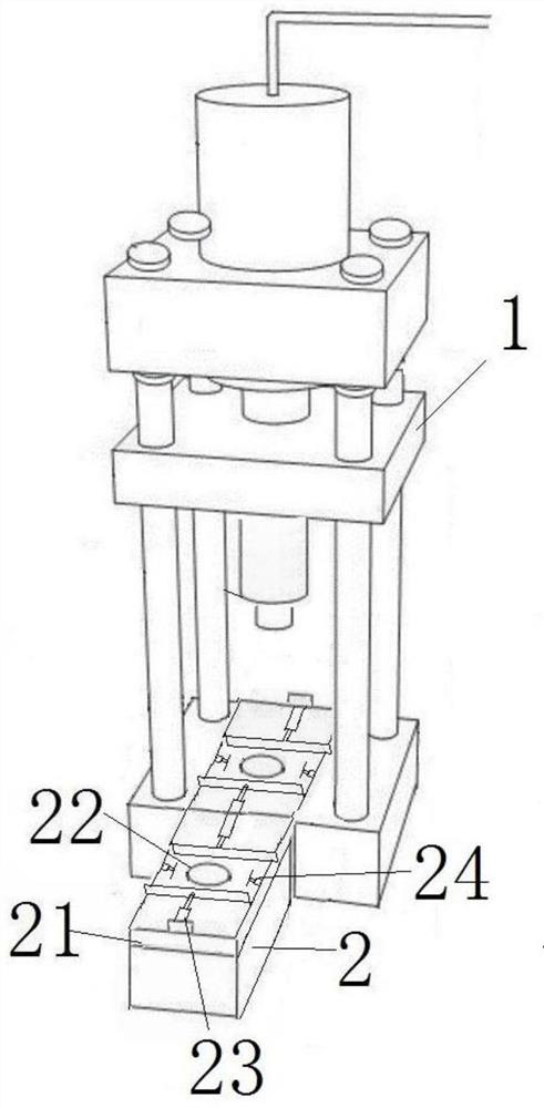
[0028] Attached below Figure 1-5 The invention is further described as figure 1 , a 3,000-ton hydraulic press, a slide rail 3 is provided under the hydraulic column 11 of the hydraulic press 1, and the slide rail 3 extends a certain distance to the left and right sides; a workbench 2 is slidably connected to the top of the slide rail 3, and the workbench 2 includes two punches Hole station, when the workbench 2 slides back and forth above the slide rail 3, the two punch stations are located directly below the hydraulic cylinder 11 in turn; each punch station includes a load-bearing platform 21, a support rod, and a pair of horizontal alignment A device 23 and a pair of longitudinal centering devices 24, and a through hole 1 22 is opened in the center of the load-bearing platform 21 .

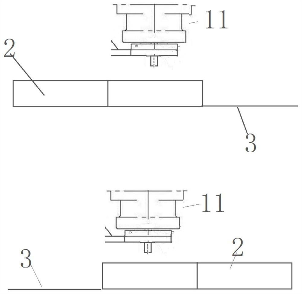
[0029] Such as figure 2 As shown, the slide rail 3 is a lead screw slide rail, and one end of the lead screw slide rail is connected to a servo motor drive device. Through the servo motor d...

Embodiment 2

[0047] The difference between this embodiment and Embodiment 1 is that both the horizontal centering device 23 and the longitudinal centering device 24 are cylinders with displacement sensors.

Embodiment 3

[0049] The difference between this embodiment and Embodiment 1 is that both the horizontal centering device 23 and the longitudinal centering device 24 are electric telescopic rods with displacement sensors.


PUM


Abstract

The invention belongs to the technical field of metal forging equipment, and particularly relates to a 3000-ton oil press punching method. The 3000-ton oil press punching method has the advantages andpositive effects that (1) in the process that a workbench slides back and forth above a sliding rail, two punching stations are located under a hydraulic cylinder in turn; to-be-forged piece preparation, punching and forged piece taking-away are sequentially conducted on each punching station, and continuous forging and punching are achieved without building a conveying chain which is large in occupied area; (2) the to-be-forged piece is transversely and longitudinally centered (relative to a through hole I of the punching station) at the punching station far away from the hydraulic column, the punching operation is not influenced in the centering process, and the centering precision is high; and (3) a punch die is placed in the tray of a mechanical swing arm, so that the punch die replacement efficiency is high.

Description

technical field [0001] The patent of the invention belongs to the technical field of metal forging equipment, and specifically relates to a punching method of a 3,000-ton hydraulic press. Background technique [0002] Forging is a processing method that uses forging machinery to apply pressure to metal blanks to cause plastic deformation to obtain forgings with certain mechanical properties, certain shapes and sizes. It is one of the two major components of forging (forging and stamping). Forging can eliminate defects such as as-cast porosity produced in the metal smelting process and optimize the microstructure. At the same time, due to the preservation of complete metal flow lines, the mechanical properties of forgings are generally better than castings of the same material. [0003] There are many problems in the use of forging and punching devices (such as 3000 tons of hydraulic presses). For example, after punching the forgings, it is necessary to take out the punched f...

Claims


Application Information

Patent Timeline
Patent Type & Authority Applications(China)
IPC IPC(8): B21D28/34B21D43/00B21D43/13B21D37/10
CPCB21D28/34B21D43/003B21D43/13B21D37/10
Inventor 柏民
Owner 山东荣升重型机械股份有限公司
Why Eureka
Try Eureka