An automatic clamping device for processing an inner-expansion yarn feeding tube

A clamping device and yarn feeding bobbin technology, applied in workpiece clamping devices, manufacturing tools, chucks, etc., can solve problems such as surface damage of yarn feeding bobbins

Active Publication Date: 2022-07-01
FUJIAN UNIV OF TECH
View PDF9 Cites 0 Cited by
  • Summary
  • Abstract
  • Description
  • Claims
  • Application Information

AI Technical Summary

Problems solved by technology

This device is used to clamp the yarn feeding tube, which will leave obvious clamping marks on the surface of the yarn feeding tube, thus causing damage to the surface of the yarn feeding tube

Method used


Image

  • An automatic clamping device for processing an inner-expansion yarn feeding tube
  • An automatic clamping device for processing an inner-expansion yarn feeding tube
  • An automatic clamping device for processing an inner-expansion yarn feeding tube

Examples


Embodiment 1

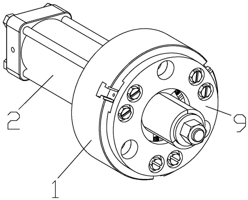
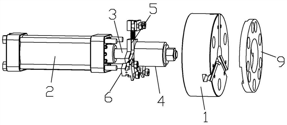
[0030] Refer to the attached Figure 1-7 : This automatic clamping device for internal expansion type yarn feeding tube processing includes a chuck 1, a driving part 2, a guide rod 3, a clamping unit 4, a moving unit 5 and a limit unit 6, a moving unit 5 and a limit unit 6 The number of the three is equal and there are at least three. The driving member 2 is arranged on the chuck 1 and is used to drive the guide rod 3 to move linearly along its axis. On the upper surface, the ejector 7 is placed inside, and when the guide rod 3 moves linearly, the clamping unit 4 is opened or closed by the ejector 7, and the moving unit 5 connects the clamping unit 4 and the chuck 1, and can move along the The radial linear movement of the chuck 1, the limit unit 6 connects the moving unit 5 and the chuck 1, and exists in the path of the moving unit 5 when the chuck 1 performs the radial linear movement and is used to prevent the moving unit 5 from overtravel. The disk 1 has a first guide str...

Embodiment 2

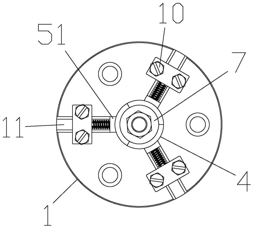
[0039] Refer to the attached Figure 8 , 9 : The first matching structure 51 is slidingly engaged with the first guide structure 11 , and the first guide structure 11 laterally protrudes / recesses along the left and right sides of the first matching structure 51 , and the first matching structure 51 extends along the left and right sides of the first guide structure 11 . Lateral concave / convex on side surfaces. Considering that when the mobile unit 5 slides on the first guide structure 11 through the first matching structure 51, only relying on the friction force alone cannot guarantee the connection of the first matching structure 51, that is, it is easy to come out of the first guide structure 11, Therefore, the two realize anti-separation by setting a protruding / recessing or a recessed / protruding structure in themselves. The protrusion here can be a round-shaped bump, and the depression can be a rectangular-shaped groove, so that the bump is inserted into the concave. so a...

Embodiment 3

[0041] Refer to the attached Figure 10 , 11 : The first matching structure 51 is slidingly engaged with the first guide structure 11 , and the first guide structure 11 laterally protrudes / recesses along the left and right sides of the first matching structure 51 , and the first matching structure 51 extends along the left and right sides of the first guide structure 11 . Lateral concave / convex on side surfaces. For the purpose of Embodiment 2, the protrusions here can be rectangular bumps, and the depressions can be rectangular grooves. Compared with the structure of Embodiment 2, the difference between the rectangular bumps and the rectangular grooves The contact surface between them is larger, so that the degree of cooperation is higher, so that the movement fluency of the mobile unit 5 is higher.


PUM


Abstract

An automatic clamping device for processing an inner-expansion yarn feeding tube comprises a chuck, a driving part, a guide rod, a clamping unit, a moving unit and a limit unit. The upper surface of the chuck is placed inside the ejector, and when the guide rod moves linearly, the clamping unit is opened or closed by the ejector. The unit has a second guide structure that makes the moving unit move linearly along the axis, and the moving unit has a first matching structure and a second matching structure matched with the first guide structure and the second guide structure. The beneficial effects of the invention are that it is easy to realize automatic centering when the yarn feeding tube is clamped, and the machining accuracy of the yarn feeding tube is ensured; the structure is easy to install and adjust, and the internal expansion force is reliable and adjustable; damage; the device can be automatically reset after the workpiece is processed, which is convenient for re-processing and clamping, and meets the needs of continuous processing.

Description

technical field [0001] The invention relates to the field of textile machinery, in particular to an automatic clamping device for processing an internal expansion type yarn feeding tube. Background technique [0002] The yarn feeding bobbin is an important part in the computerized flat knitting machine. In order to ensure the stability in the high-speed working process, its coaxiality is required to be high, and it needs high centering during processing and clamping. [0003] Publication No. CN209288317U discloses a yarn feeding bobbin tooling fixture, which includes a pull rod and a chuck, the end of the pull rod is provided with a push block, and the chuck includes a cavity and surrounds the cavity and is directed from the cavity to the outside. The track groove extends from the side of the chuck, and the track groove is provided with a claw, the claw includes a push surface that abuts against the push block, the push surface forms an acute angle with the axis of the pull ...

Claims


Application Information

Patent Timeline
Patent Type & Authority Patents(China)
IPC IPC(8): B23B31/02B23B31/16B23B31/30B25B11/00
CPCB23B31/02B23B31/16B23B31/30B25B11/00
Inventor 张宁张帅杜金隆谈健君张炜练国富
Owner FUJIAN UNIV OF TECH
Why Eureka
Try Eureka