Internal expansion type automatic clamping device for yarn feeding pipe processing

A technology of clamping device and yarn feeding tube, which is applied in the direction of workpiece clamping device, manufacturing tool, chuck, etc., can solve the problems such as surface damage of yarn feeding tube, avoid damage, adjust the internal expansion force, ensure The effect of machining accuracy

Active Publication Date: 2021-03-19
FUJIAN UNIV OF TECH
View PDF9 Cites 0 Cited by
  • Summary
  • Abstract
  • Description
  • Claims
  • Application Information

AI Technical Summary

Problems solved by technology

This device is used to clamp the yarn feeding tube, which will leave obvious clamping marks on the surface of the yarn feeding tube, thus causing damage to the surface of the yarn feeding tube

Method used


Image

  • Internal expansion type automatic clamping device for yarn feeding pipe processing
  • Internal expansion type automatic clamping device for yarn feeding pipe processing
  • Internal expansion type automatic clamping device for yarn feeding pipe processing

Examples


Embodiment 1

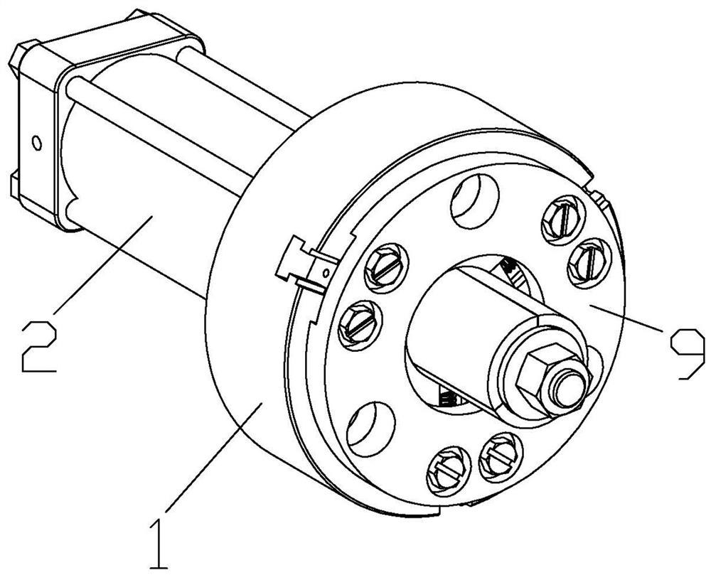
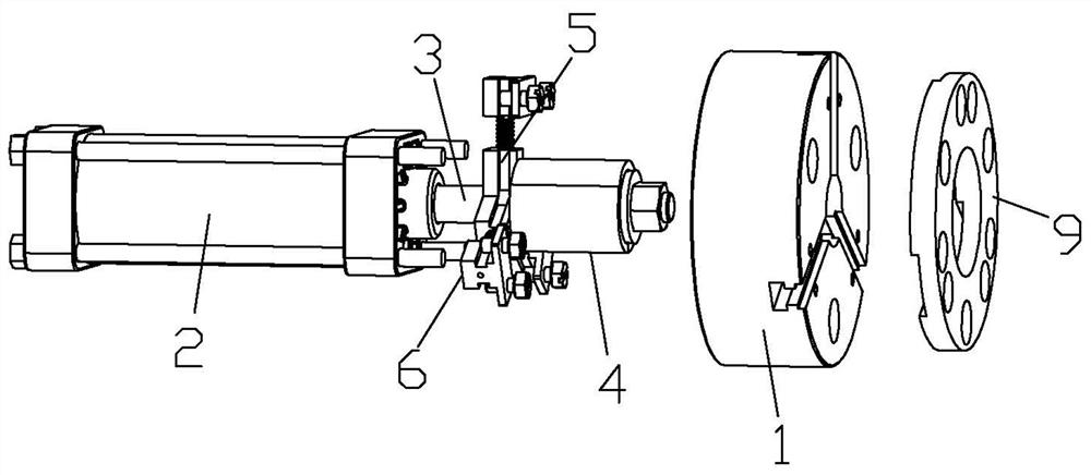
[0030] Refer to attached Figure 1-7 : This internal expansion type yarn feeding tube processing automatic clamping device includes a chuck 1, a driver 2, a guide rod 3, a clamping unit 4, a moving unit 5 and a limiting unit 6, a moving unit 5 and a limiting unit 6 The number of the three is equal and there are at least three. The driving member 2 is arranged on the chuck 1 and is used to drive the guide rod 3 to move linearly along its axis. One end of the guide rod 3 has a top-opening member 7, and the clamping unit 4 is located The upper surface is also for the opening part 7 to be placed inside, and the clamping unit 4 is opened or closed by the opening part 7 when the guide rod 3 moves linearly, the moving unit 5 connects the clamping unit 4 and the chuck 1, and can be moved along the The radial linear movement of the chuck 1, the limit unit 6 connects the mobile unit 5 and the chuck 1, and exists in the path of the mobile unit 5 when the chuck 1 makes a radial linear mot...

Embodiment 2

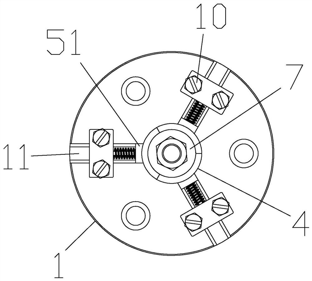
[0039] Refer to attached Figure 8 , 9 : the first matching structure 51 is slidingly matched with the first guiding structure 11, and the first guiding structure 11 protrudes / recesses laterally along the left and right sides of the first matching structure 51, and the first matching structure 51 moves along the left and right sides of the first guiding structure 11. The lateral surface is concave / convex laterally. Considering that when the mobile unit 5 slides on the first guiding structure 11 through the first matching structure 51, the connection of the first matching structure 51 cannot be guaranteed by only relying on the friction force of the two, that is, it is easy to escape from the first guiding structure 11, Therefore, both of them realize anti-off by setting protrusion / depression or depression / protrusion structure on themselves. The protrusion here can be a round bump, and the depression can be a rectangular groove, so that the protrusion can be inserted into the ...

Embodiment 3

[0041] Refer to attached Figure 10 , 11 : the first matching structure 51 is slidingly matched with the first guiding structure 11, and the first guiding structure 11 protrudes / recesses laterally along the left and right sides of the first matching structure 51, and the first matching structure 51 moves along the left and right sides of the first guiding structure 11. The lateral surface is concave / convex laterally. Based on the purpose of Embodiment 2, the protrusion here can be a rectangular bump, and the depression can be a rectangular groove. Compared with the structure of Embodiment 2, the difference between the rectangular bump and the rectangular groove The contact surface between them is larger, so that the cooperation degree is higher, and the mobile unit 5 has a higher smoothness of movement like this.


PUM


Abstract

An internal expansion type automatic clamping device for yarn feeding pipe processing comprises a chuck, a driving piece, a guide rod, a clamping unit, a moving unit and a limiting unit. An ejecting piece is arranged at one end of the guide rod, the clamping unit is located on the upper surface of the chuck and allows the ejecting piece to be arranged therein, and the clamping unit is opened or closed through the ejecting piece when the guide rod does linear motion; and the chuck is provided with a first guide structure enabling the moving unit to linearly move in the radial direction, the limiting unit is provided with a second guide structure enabling the moving unit to linearly move along the axis, and the moving unit is provided with a first matching structure and a second matching structure which are matched with the first guide structure and the second guide structure. The internal expansion type automatic clamping device has the beneficial effects that automatic centering duringclamping of a yarn feeding pipe is easy to achieve, and the machining precision of the yarn feeding pipe is guaranteed; the structure is convenient to install and adjust, and the internal expansion force is reliable and adjustable; damage to the surface of the yarn feeding pipe can be avoided; and the device can automatically reset after a workpiece is machined, machining and clamping again are facilitated, and the continuous machining requirement is met.

Description

technical field [0001] The invention relates to the field of textile machinery, in particular to an internal expansion type automatic clamping device for yarn feeding bobbin processing. Background technique [0002] The yarn feeding tube is an important part of the computerized flat knitting machine. In order to ensure the stability in the high-speed working process, its coaxiality is required to be high, and it needs a high degree of centering during processing and clamping. [0003] Publication No. CN209288317U discloses a tooling fixture for a yarn feeding tube, which includes a pull rod and a chuck. The end of the pull rod is provided with a push block. The track groove extending from the side of the chuck, the track groove is provided with a claw, the claw includes a push surface against the push block, the push surface forms an acute angle with the axis of the pull rod, and the track The end of the groove is provided with a first stopper, the first stopper is provided...

Claims


Application Information

Patent Timeline
Patent Type & Authority Applications(China)
IPC IPC(8): B23B31/02B23B31/16B23B31/30B25B11/00
CPCB23B31/02B23B31/16B23B31/30B25B11/00
Inventor 张宁张帅杜金隆谈健君张炜练国富
Owner FUJIAN UNIV OF TECH
Why Eureka
Try Eureka