Fluted disc rotating positioning mechanism of milling cutter processing machine

A positioning mechanism and processing machine technology, applied in metal processing mechanical parts, positioning devices, precision positioning equipment and other directions, can solve the problem of low rotation accuracy of the clamping device, avoid frequent debugging of the machine, avoid tooth damage, transmission effect Good results

Pending Publication Date: 2021-03-19
GUANGDONG UCAN ROBOT TECH CO LTD
View PDF5 Cites 0 Cited by
  • Summary
  • Abstract
  • Description
  • Claims
  • Application Information

AI Technical Summary

Problems solved by technology

[0006] The technical problem to be solved by the present invention is to provide a toothed disc rotation positioning mechanism of a milling cutter processing machine, which can realize the elastic meshing of the gears, effectively avoid tooth damage, improve the precision of gear meshing, avoid slipping, and have a good transmission effect , effectively solve the problem of low rotation accuracy of the clamping device, avoid frequent machine debugging, high machining accuracy of the workpiece, and improve work efficiency

Method used


Image

  • Fluted disc rotating positioning mechanism of milling cutter processing machine
  • Fluted disc rotating positioning mechanism of milling cutter processing machine
  • Fluted disc rotating positioning mechanism of milling cutter processing machine

Examples


Embodiment Construction

[0025] In order to facilitate the understanding of those skilled in the art, the present invention will be further described below in conjunction with the embodiments and accompanying drawings, and the contents mentioned in the embodiments are not intended to limit the present invention.

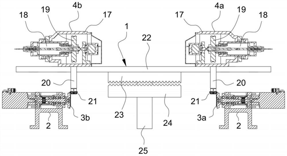
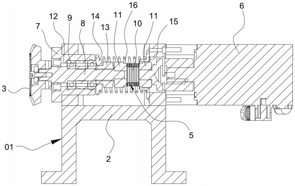
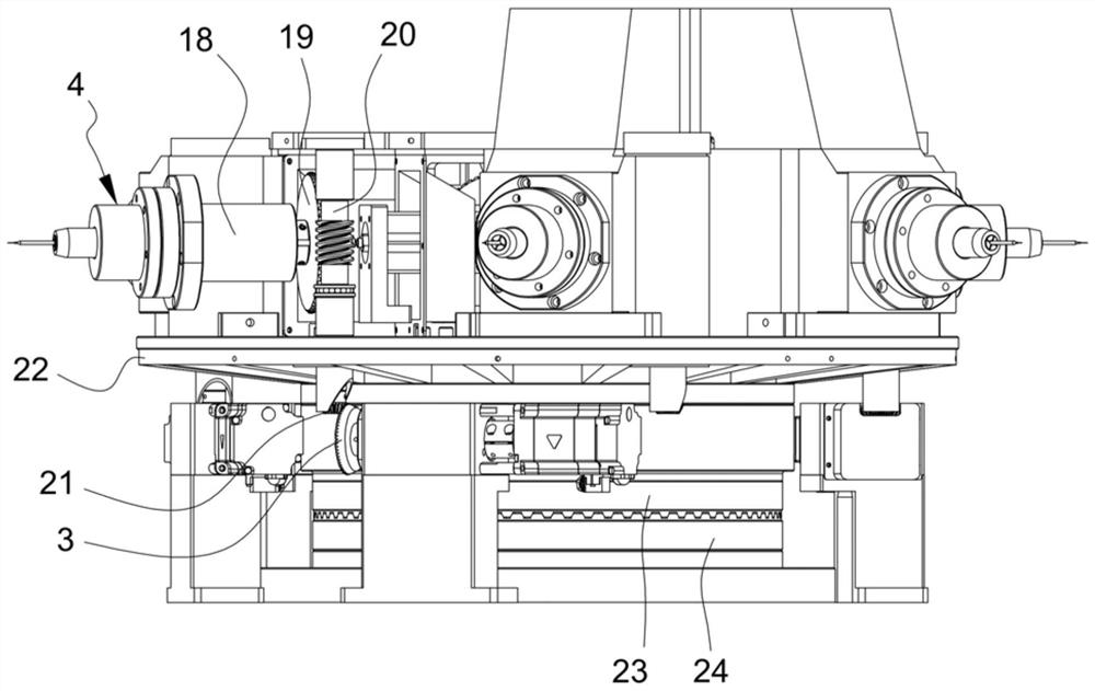
[0026] Such as Figure 1 to Figure 5 As shown, the tooth plate rotation positioning mechanism of a milling cutter processing machine provided by the present invention includes a rotary table 1, a gear elastic rotation drive device 01 and a plurality of clamping devices 4 arranged on the rotary table 1, and the gear The elastic rotation drive device 01 includes a drive base 2 and a first gear 3 that is rotatably mounted on the drive base 2. An elastic connector 5 is installed on one end of the first gear 3, and the elastic connector 5 is connected with a rotation driver 6. The rotation driver 6 Used to drive the elastic connecting member 5 and the first gear 3 to rotate, the first gear 3 can ...


PUM


Abstract

The invention relates to the technical field of cutter machining equipment, in particular to a fluted disc rotation positioning mechanism of a milling cutter machining machine. The fluted disc rotation positioning mechanism of the milling cutter machining machine comprises a rotary workbench, a gear elastic rotation driving device and a clamping device, wherein the gear elastic rotation driving device comprises a driving base and a first gear; one end of the first gear is provided with an elastic connecting piece; the first gear can rotate around the axial center line of the first gear and elastically move in the direction of the axial center line of the first gear; the first gear is in elastic rotation drive connection with the clamping device; and the rotary workbench comprises a workbench plate, a first fluted disc, a second fluted disc and a workbench driving assembly. According to the fluted disc rotation positioning mechanism of the milling cutter machining machine provided by the invention, elastic meshing of gears can be achieved, gear damage is effectively avoided, the gear meshing precision is improved, the slipping situation is avoided, the transmission effect is good, the problem that the clamping device is low in rotating precision is effectively solved, frequent debugging of a machine is avoided, the machining precision of workpieces is high, and the working efficiency is improved.

Description

technical field [0001] The invention relates to the technical field of cutting tool processing equipment, in particular to a gear plate rotation positioning mechanism of a milling cutter processing machine. Background technique [0002] A milling cutter is a rotating tool with one or more teeth for milling. When working, each tooth cuts off the allowance of the workpiece intermittently. The milling cutter is mainly used for machining planes, steps, and grooves on milling machines. , forming surfaces and cutting workpieces, etc., milling cutters are widely used in modern processing and production. [0003] In existing processing equipment, the meshing between gears is rigid meshing, which is prone to tooth damage, resulting in serious gear wear, short service life, and high maintenance costs for processing equipment. [0004] Moreover, the meshing precision of the traditional gears is not high, and the situation of slipping may occur, so that effective transmission cannot be...

Claims


Application Information

Patent Timeline
IPC IPC(8): B23Q1/25B23Q3/06B23Q16/00
CPCB23Q1/25B23Q3/06B23Q16/00
Inventor 王俊锋唐凌志李政王帅
Owner GUANGDONG UCAN ROBOT TECH CO LTD
Why Eureka
Try Eureka