Turbine blade assembling method

An assembly method and technology of turbine blades, which are applied to the supporting elements of blades, engine elements, machines/engines, etc., can solve the problems of time-consuming and laborious assembly, large assembly force, gas turbine failure, etc., so as to avoid tooth damage and improve assembly quality. , Eliminate the effect of scrap parts

Inactive Publication Date: 2020-06-16
AECC AVIATION POWER CO LTD
View PDF2 Cites 0 Cited by
  • Summary
  • Abstract
  • Description
  • Claims
  • Application Information

AI Technical Summary

Problems solved by technology

[0003] The blade shroud of a gas turbine blade is sawtooth-shaped, and the lengths of the two blade shrouds are inconsistent. During assembly, due to the design structure with pre-twisting, the long and short sides of the blade shroud are mutually constrained, and the assembly is time-consuming and laborious.
At the same time, because the inlet and exhaust sides of the blade body cannot bear force during assembly, and the assembly force is relatively large, the assembly can only be performed by knocking on the mortise and tooth parts of the blade.
This design structure determines that the assembly method is likely to cause local stress concentration at the tenon teeth of the blade and even produce micro-cracks or initial cracks, and the fatigue resistance of the blade is reduced
[0004] During the working process of the blade, the blade is affected by factors such as centrifugal force, vibration and temperature load, and fatigue cracks are prone to occur at the damaged part of the blade. Teeth fractured, eventually causing the gas turbine to fail

Method used


Image

  • Turbine blade assembling method
  • Turbine blade assembling method
  • Turbine blade assembling method

Examples


Embodiment

[0046] A method for assembling a turbine blade of a gas turbine, comprising the following steps:

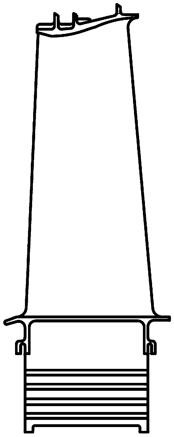
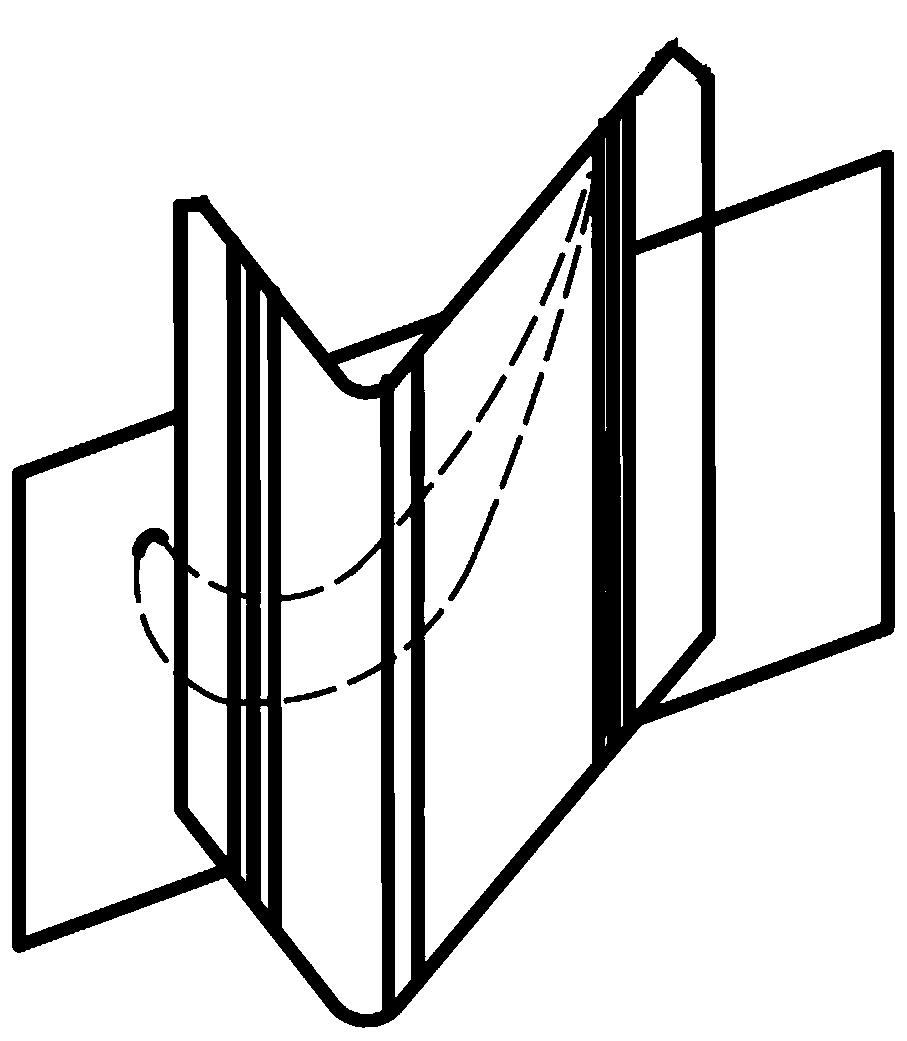
[0047] Step 1: Weigh the blade on an electronic balance; the shape of the blade is as figure 1 and figure 2 As shown; the crown is serrated, and the lengths of the two serrations of the crown are inconsistent, the design structure is pre-twisted during assembly, and the long and short sides of the crown of the blade are mutually constrained;

[0048] Step 2: Sort the leaves according to weight, the heaviest leaf is No. 1, and sort them in order;

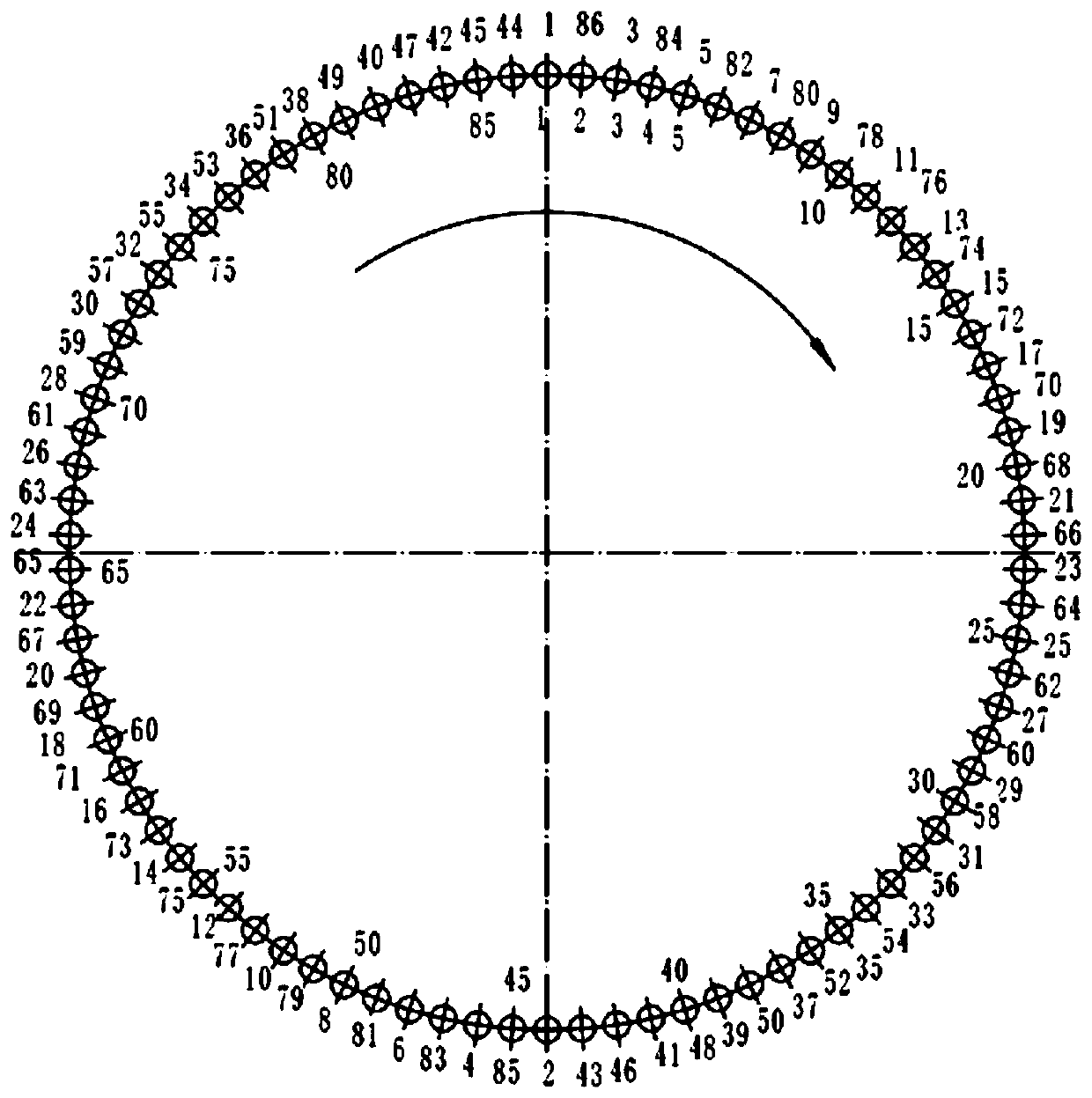
[0049] Step 3: Follow the image 3 Correspondence Put the blades into the corresponding turbine disk tenons, and check the swing of a single blade, image 3 The serial number of the inner ring is the serial number of the roulette slot, and the serial number of the outer ring is the serial number of the blade weight, and the swing amount should not be less than 0.25% of the blade length.

[0050] Step 4: Repeat step 3 to check the s...


PUM


Abstract

The invention discloses a turbine blade assembling method. The turbine blade assembling method comprises the following steps that to-be-assembled blades are weighed; the blades are sorted according tothe weight, the heaviest blade is numbered as 1, and the blades are sequentially numbered as 1,2,...N from weight to light, wherein N is the total number of to-be-assembled blades on a turbine disc;the blades correspond to tenon grooves of the turbine disc in position generally in the clockwise or counterclockwise direction, and the adjacent numbers of blades are sequentially and correspondinglymounted according to the central symmetrical position, wherein the odevity of the numbers of every two adjacent blades is different; the swinging amount of all the blades is checked; the blades are sequentially mounted into the tenon grooves of the turbine disc according to the corresponding mounting relation and sequence; and tenon parts of the blades are sequentially knocked in the blade assembling direction till the end faces of all blade tenons are flush with the end faces of the tenon grooves of the turbine disc. The assembling quality of the turbine blades is improved, damage to tenon teeth of the blades is avoided, part scrap caused by assembling damage is eliminated, the quality of the assembled turbine blades is stable, and safe and reliable operation of a gas turbine can be guaranteed.

Description

technical field [0001] The invention belongs to the technical field of assembly, and in particular relates to a turbine blade assembly method. Background technique [0002] The turbine blade of a gas turbine is one of the parts that bear the most severe temperature load and the worst working environment in the gas turbine. It not only bears a large centrifugal load, thermal load, aerodynamic load, etc., but also bears gas corrosion, oxidation, etc. . Due to its long-term operation under high temperature, high pressure, and high speed conditions, it has high requirements for the assembly quality of turbine blades. Turbine blades are an important part of a gas turbine, and whether they can operate normally is an important factor that determines whether the gas turbine can work normally. [0003] The blade shroud of a gas turbine blade is serrated, and the lengths of the two blade shrouds are inconsistent. Due to the pre-twisted design structure during assembly, the long and ...

Claims


Application Information

Patent Timeline
Patent Type & Authority Applications(China)
IPC IPC(8): B23P15/04F01D5/30
CPCB23P15/04F01D5/3007
Inventor 陈伟周敏李晨殷倩雯常勇赵小林强美宁张澜禹
Owner AECC AVIATION POWER CO LTD
Why Eureka
Try Eureka