Automatic locking universal clamping mechanism for multi-station milling cutter machining machine

An automatic locking and processing machine technology, used in metal processing machinery parts, metal processing equipment, clamping and other directions, can solve the problems of scratching the milling cutter material bar, prone to tooth damage, gear wear, etc., to prevent poor contact , prolong the service life, the effect of simple debugging operation

Active Publication Date: 2021-04-27
GUANGDONG UCAN ROBOT TECH CO LTD
View PDF11 Cites 0 Cited by
  • Summary
  • Abstract
  • Description
  • Claims
  • Application Information

AI Technical Summary

Problems solved by technology

[0002] The milling cutter rod is fixedly inserted in the clamping mechanism during the milling process. The clamping mechanism is equipped with a collet for clamping the milling cutter rod. The traditional clamping mechanism is a clamping method for the milling cutter rod It is a rigid clamping method, which means that the clamped milling cutter rod is not allowed to swing. After the milling cutter rod is installed on the machine, the milling cutter rod is pressed by the pressing mechanism. The rigid clamping method has a great influence on the accuracy of machine debugging. The requirements are extremely high, and the allowable position error between the milling cutter rod and the holding mechanism is very small, otherwise it is easy to scratch the milling cutter rod when pressing the milling cutter rod, the collet wears seriously, or because the position error is large The large size leads to substandard processing accuracy, which further leads to low precision and low yield of finished milling cutters, which cannot meet modern production needs.
[0003] In the existing milling cutter processing equipment, the meshing between gears is rigid meshing, which is prone to tooth damage, resulting in serious gear wear, short service life, and high maintenance costs for processing equipment
Moreover, the meshing accuracy of traditional gears is not high, and slipping will occur, which cannot achieve effective transmission, and the transmission effect is poor

Method used


Image

  • Automatic locking universal clamping mechanism for multi-station milling cutter machining machine
  • Automatic locking universal clamping mechanism for multi-station milling cutter machining machine
  • Automatic locking universal clamping mechanism for multi-station milling cutter machining machine

Examples


Embodiment Construction

[0033] In order to facilitate the understanding of those skilled in the art, the present invention will be further described below in conjunction with the embodiments and accompanying drawings, and the contents mentioned in the embodiments are not intended to limit the present invention.

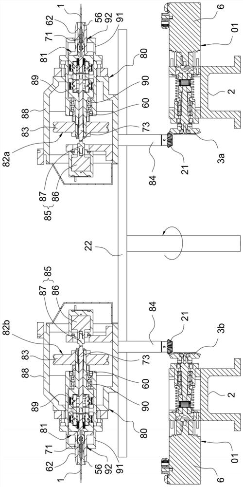
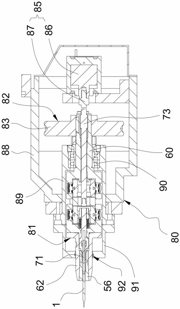
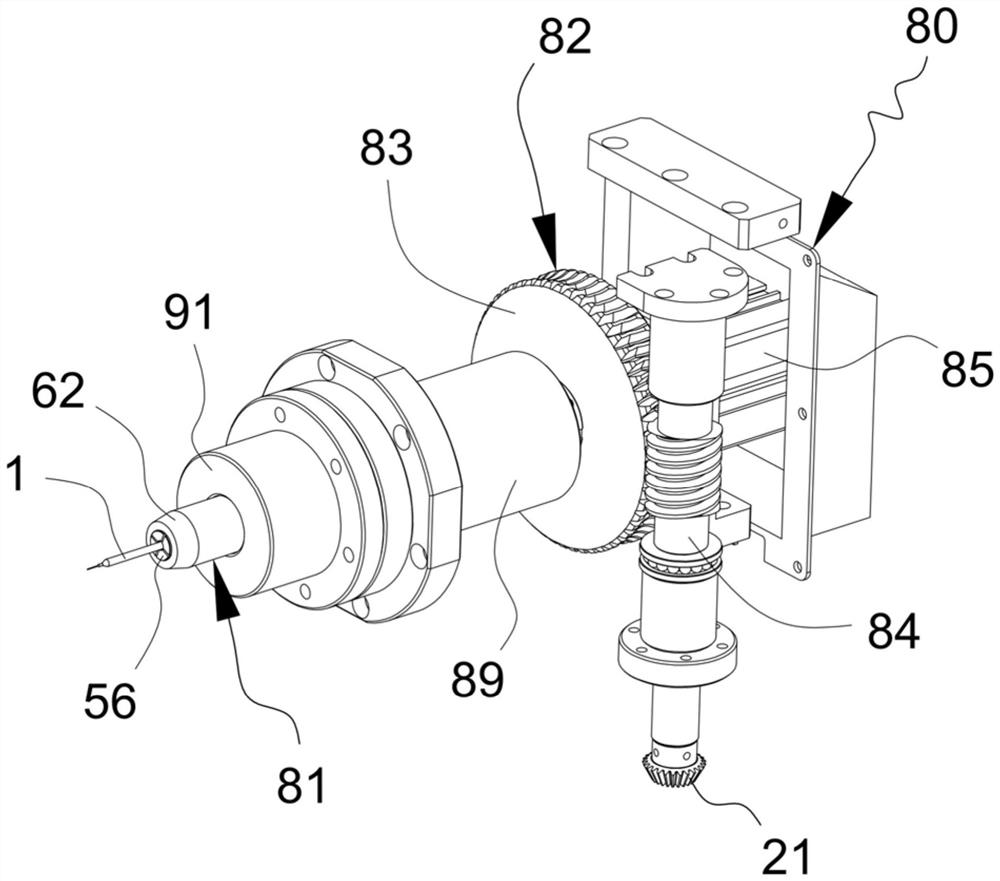
[0034] Such as Figure 1 to Figure 11 As shown, the present invention provides an automatic locking universal clamping mechanism for a multi-station milling cutter processing machine, which includes a rotary table 22, a plurality of universal clamping rotating structures 80 and a plurality of gears for elastic rotation The driving structure 01; the universal clamping rotating structure 80 includes a universal clamping device 81 and a rotating drive device 82, the universal clamping device 81 includes a central fixed block 58, and first rotating and mounted on both ends of the central fixed block 58, respectively. The movable part 59 and the second movable part 60, the central fixed block 58,...


PUM


Abstract

The invention relates to the technical field of cutter machining equipment, in particular to an automatic locking universal clamping mechanism for a multi-station milling cutter machining machine. The mechanism comprises a rotary worktable, a universal clamping rotary structure and a gear elastic rotation driving structure, wherein the universal clamping rotary structure comprises a universal clamping device and a rotation driving device, the universal clamping device comprises a central fixed block, a first movable part and a second movable part, the first movable part is provided with a collet sleeve part, a collet is movably installed in the collet sleeve part, and an elastic pull rod part is installed in the first movable part; and the gear elastic rotation driving structure comprises a driving base and a first gear, and the first gear is provided with an elastic connecting piece. The requirement for machine debugging precision is low, automatic rotation of slotting of a milling cutter bar is achieved, the precision and yield of finished milling cutters are high, elastic meshing of gears can be achieved, tooth damage is effectively avoided, the meshing precision of the gears is improved, slipping is avoided, and the transmission effect is good.

Description

technical field [0001] The invention relates to the technical field of cutting tool processing equipment, in particular to an automatic locking universal clamping mechanism for a multi-station milling cutter processing machine. Background technique [0002] The milling cutter rod is fixedly inserted in the clamping mechanism during the milling process. The clamping mechanism is equipped with a collet for clamping the milling cutter rod. The traditional clamping mechanism is a clamping method for the milling cutter rod It is a rigid clamping method, which means that the clamped milling cutter rod is not allowed to swing. After the milling cutter rod is installed on the machine, the milling cutter rod is pressed by the pressing mechanism. The rigid clamping method has a great influence on the accuracy of machine debugging. The requirements are extremely high, and the allowable position error between the milling cutter rod and the holding mechanism is very small, otherwise it i...

Claims


Application Information

Patent Timeline
Patent Type & Authority Applications(China)
IPC IPC(8): B23Q3/06B23Q11/08
CPCB23Q3/062B23Q11/08
Inventor 王俊锋唐凌志李政王帅
Owner GUANGDONG UCAN ROBOT TECH CO LTD
Why Eureka
Try Eureka