Rotary control center mechanism of multi-station milling cutter machining machine

A control center and processing machine technology, which is applied in the direction of metal processing machinery parts, metal processing equipment, milling machines, etc., can solve problems such as slipping, easy tooth damage, scratching milling cutter rods, etc., so as to avoid debugging the machine and prolong its use The effect of life expectancy and labor cost reduction

Active Publication Date: 2021-05-28
GUANGDONG UCAN ROBOT TECH CO LTD
View PDF10 Cites 0 Cited by
  • Summary
  • Abstract
  • Description
  • Claims
  • Application Information

AI Technical Summary

Problems solved by technology

[0002] The milling cutter rod is fixedly inserted in the clamping mechanism during the milling process. The clamping mechanism is equipped with a collet for clamping the milling cutter rod. The traditional clamping mechanism is a clamping method for the milling cutter rod It is a rigid clamping method, which means that the clamped milling cutter rod is not allowed to swing. After the milling cutter rod is installed on the machine, the milling cutter rod is pressed by the pressing mechanism. The rigid clamping method has a great influence on the accuracy of machine debugging. The requirements are extremely high, and the allowable position error between the milling cutter rod and the holding mechanism is very small, otherwise it is easy to scratch the milling cutter rod when pressing the milling cutter rod, the collet wears seriously, or because the position error is large The large size leads to substandard processing accuracy, which further leads to low precision and low yield of finished milling cutters, which cannot meet modern production needs.
[0003] In the existing milling cutter processing equipment, a rotating disk is usually installed, and the rotation of the rotating disk drives the clamping device to rotate to the preset station. However, the rotation accuracy of the rotating disk is relatively low, and it is impossible to make the clamping device Accurately stop to the specified position, the position error of each stop action, after many times of accumulation, the error is getting bigger and bigger, the machining accuracy of the milling cutter is low, at this time it is necessary to re-adjust the machine, frequent machine adjustment leads to low work efficiency, high labor cost
[0004] In the existing milling cutter processing equipment, the meshing between gears is rigid meshing, which is prone to tooth damage, resulting in serious gear wear, short service life, and high maintenance costs for processing equipment
Moreover, the meshing accuracy of traditional gears is not high, and slipping will occur, which cannot achieve effective transmission, and the transmission effect is poor

Method used


Image

  • Rotary control center mechanism of multi-station milling cutter machining machine
  • Rotary control center mechanism of multi-station milling cutter machining machine
  • Rotary control center mechanism of multi-station milling cutter machining machine

Examples


Embodiment Construction

[0039]In order to facilitate the understanding of those skilled in the art, the following description of the invention will be made in conjunction with the drawings, and the contents mentioned in the present invention are not limited.

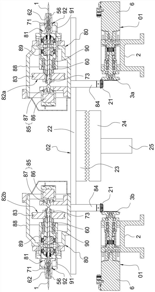
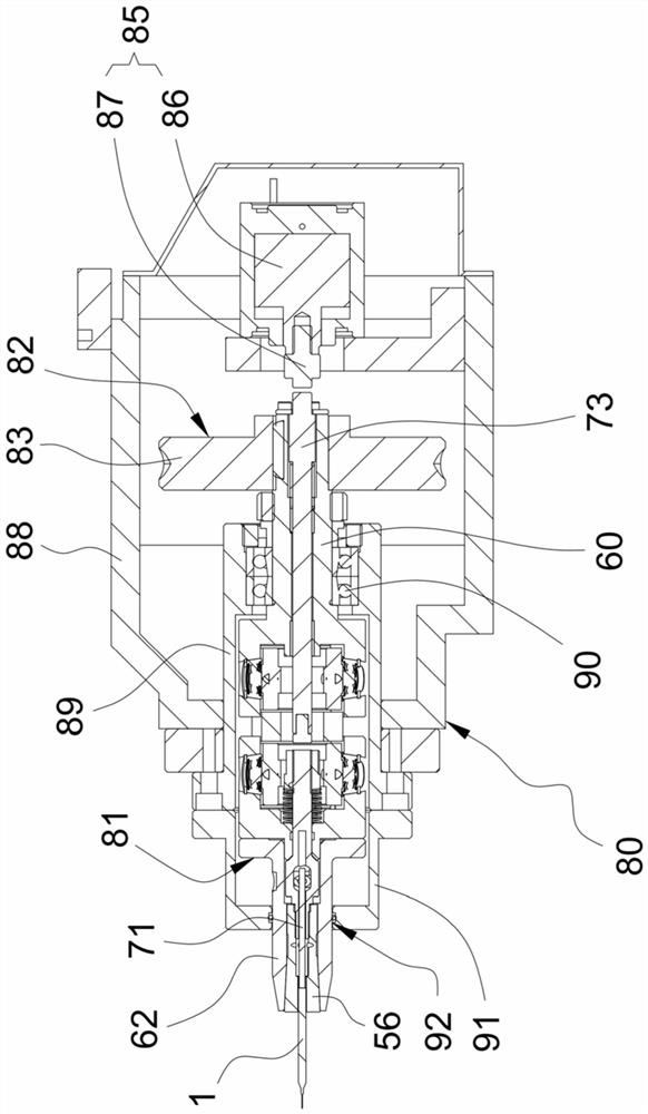
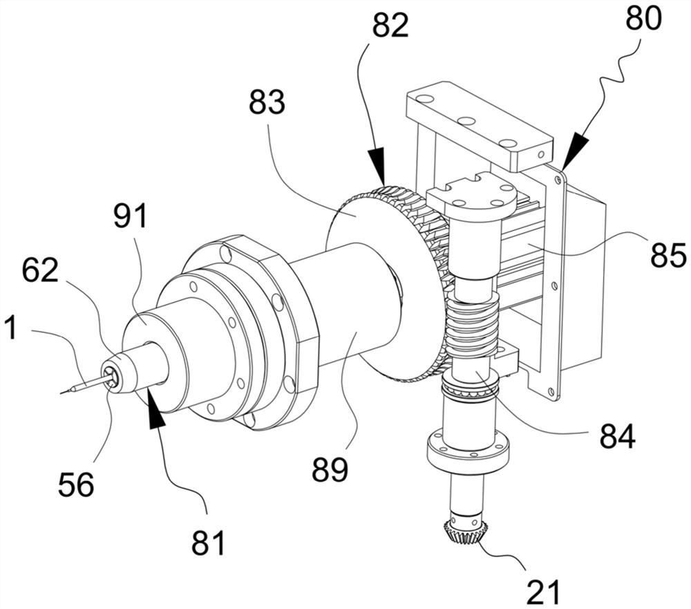
[0040]Such asFigure 1 to 15As shown, a rotational control center mechanism of a multi-station milling cutter, including a rack 39, a turntable device 02, a plurality of universal jaw rotation structures 80 and a plurality of gear elastic rotation drive structures 01 The turntable apparatus 02 includes a sliding rotation of the working table 22, which is fixed to the lower end of the working table 22, fixed to the first tooth disk disposed at the lower end of the workbed plate 22. The second tooth disk 24 meshed with the first tooth disc 23 and the table drive assembly 25 driven by the support shaft 29, and the support shaft 29 is provided with a sliding rotating member 40, and the table drive assembly 25 is used to drive support. The shaft 29 is slid in...


PUM


Abstract

The invention relates to the technical field of cutter machining equipment, in particular to a rotary control center mechanism of a multi-station milling cutter machining machine. The rotary control center mechanism comprises a machine frame, a rotary disc device, universal material clamping rotation structures and gear elastic rotation driving structures, and the rotary disc device comprises a working table plate, a supporting shaft rod, a first fluted disc and a second fluted disc. Each universal material clamping device comprises a central fixed block, a first movable part and a second movable part, and an elastic pull rod part is installed in each first movable part. Each gear elastic rotation driving structure comprises a driving base and a first gear. A clamped and installed milling cutter material bar can swing, the requirement for the precision of machine debugging is low, automatic rotation of the milling cutter material bar in the grooving process is achieved, the precision of a finished product milling cutter is high, the yield is high, frequent machine debugging is avoided, the working efficiency is improved, elastic meshing of gears can also be achieved, teeth are effectively prevented from being damaged, the meshing precision of the gears is improved, the slipping situation is avoided, and the transmission effect is good.

Description

Technical field[0001]The present invention relates to the technical field of tool processing equipment, in particular, refers to a rotational control center mechanism of a multi-station milling cutter processing machine.Background technique[0002]The milling cutter rod is fixedly inserted into the jacket mechanism during the milling process, and the jacket mechanism is provided with a barrier to clamp the milling rod, and the conventional jaw mechanism is a clamping method for the milling cutter. For the hard clamping mode, that is, the cladding cutter rod is not allowed to swing, and the milling cutter rod is mounted to the gripping mechanism to press the milling tool rod, the hard clamping mode on the accuracy of the machine debugging The positional error between the permissible milling cutter rod and the pressing mechanism is very small, otherwise it is easy to scratch the milling rod, and the wear of the cartridge is severe, or because the position error is more It is highly caus...

Claims


Application Information

Patent Timeline
Patent Type & Authority Applications(China)
IPC IPC(8): B23Q3/06B23Q3/10B23Q1/26B23C1/14
CPCB23Q3/06B23Q3/061B23Q1/26B23C1/14B23Q2703/08B23Q2703/12
Inventor 王俊锋唐凌志李政王帅
Owner GUANGDONG UCAN ROBOT TECH CO LTD
Why Eureka
Try Eureka