
Double-motor single-speed hub speed reduction parallel-axis electric drive axle

A wheel-side reducer and parallel shaft technology, which is applied in the directions of axles, wheels, electric power devices, etc., can solve the problems of difficult to balance the power and economy of the whole vehicle, the layout space of the large chassis structure, and the narrow efficient working area of ​​the motor. , to achieve the effect of flexible layout of axles, saving chassis space and improving vehicle stability

Pending Publication Date: 2021-03-19
DONGFENG DANA AXLE
View PDF0 Cites 0 Cited by
  • Summary
  • Abstract
  • Description
  • Claims
  • Application Information

AI Technical Summary

Problems solved by technology

At present, the more mature and widely used electric drive technology in the domestic and foreign markets is based on the transmission system composed of a single motor and a differential reducer. The centralized drive form of a single motor mainly relies on the rigid power transmission of gears and couplings. The loss in the process is almost the same as that of ordinary fuel vehicles, with high energy loss, low transmission efficiency and weak power
In addition, in the electric drive axle with single-speed parallel shaft and wheel-side deceleration, automobile manufacturers use a drive motor. In order to meet the power requirements, the volume and quality of the motor are relatively large, which not only occupies a large space for the layout of the chassis structure , and also affects the number of battery layouts; it also makes the maximum speed of the motor generally low, the high-efficiency working area of ​​the motor is narrow, and the energy utilization rate is low, resulting in a short driving range of the vehicle, and it is difficult to balance the power and economy of the vehicle

Method used


Image

  • Double-motor single-speed hub speed reduction parallel-axis electric drive axle

Examples


Embodiment Construction

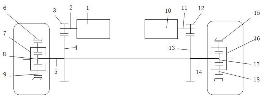
[0018] Such as figure 1 As shown, the present invention is a dual-motor single-speed pulley-side deceleration parallel-axis electric drive axle, including a first motor 1, a second motor 2, a first output half shaft 5, a second output half shaft 14, The first wheel reducer assembly, the second wheel reducer assembly, the first reducer assembly and the second reducer assembly. Wherein, the first motor 1 is installed on the first reducer assembly, and the second motor 2 is installed on the second reducer assembly. The two ends of the first output semi-shaft 5 are respectively connected with the first wheel side reducer assembly and the first reduction gear 4, and the two ends of the second output semi-shaft 14 are connected with the second wheel side reducer assembly and the second reduction gear respectively. Gear 13 is connected. The first motor 1 and the second motor 10 are drive motors of the same type, and the first motor 1 and the second motor 10 are arranged coaxially a...


PUM


Abstract

The invention discloses a double-motor single-speed hub speed reduction parallel-axis electric drive axle. The invention belongs to the technical field of new energy vehicles. The problems that an existing single motor is high in energy loss, low in transmission efficiency and poor in power performance are mainly solved. The electric drive axle is mainly characterized by comprising a first motor,a second motor, a first output half shaft, a second output half shaft, a first hub speed reducer assembly, a second hub speed reducer assembly, a first speed reducer assembly and a second speed reducer assembly; the first motor and the second motor are mounted on the first speed reducer assembly and the second speed reducer assembly respectively. The first speed reducer assembly and the second speed reducer assembly comprise meshed input gears and reduction gears; the two ends of the first output half shaft are connected with the first hub speed reducer assembly and the first reduction gear respectively, and the two ends of the second output half shaft are connected with the second hub speed reducer assembly and the second reduction gear respectively; and the first output half shaft and the second output half shaft are parallel to the first motor shaft and the second motor shaft. The electric drive axle has the advantages of being simple in structure and capable of improving passing ability and dynamic property, and is mainly used for single-speed hub speed reduction parallel-axis electric drive axle.

Description

technical field [0001] The invention belongs to the technical field of new energy vehicles. In particular, it relates to a double-motor single-speed pulley-side deceleration parallel-axis electric drive axle. Background technique [0002] As more and more attention is paid to automobile exhaust pollution and energy consumption around the world, new energy vehicles have become the key research and development models of automobile manufacturers in various countries. The power system of the whole vehicle has also changed from the original engine + gearbox + traditional axle to the current motor + transmission axle to provide power. At present, the more mature and widely used electric drive technology in the domestic and foreign markets is based on the transmission system composed of a single motor and a differential reducer. The centralized drive form of a single motor mainly relies on the rigid power transmission of gears and couplings. The loss in the process is almost the ...

Claims


Application Information

Patent Timeline
IPC IPC(8): B60B35/12B60K17/04B60K1/02
CPCB60B35/125B60K1/02B60K17/046
Inventor 赵正飞凌志峰胡恒唐铭翰王志强
Owner DONGFENG DANA AXLE
Learn More