Hoisting device for prefabricated reinforcement cage

A hoisting device and steel cage technology, which is applied in transportation and packaging, load hanging components, construction, etc., can solve problems such as collapsed holes, long construction period, and deformation of the steel cage size, and achieve the effect of increasing the bearing area

Active Publication Date: 2021-03-19
湖北才汇投资咨询有限公司
View PDF8 Cites 2 Cited by
  • Summary
  • Abstract
  • Description
  • Claims
  • Application Information

AI Technical Summary

Problems solved by technology

[0003] In the current construction method of concrete piles and steel pipe columns, in the construction process, it is necessary to wait for the concrete pile to harden and go deep into the pile hole to remove the inferior layer on the upper layer of the concrete pile, and then carry out the construction of the steel pipe column, which has a long construction period and high cost; The connection strength between concrete piles and steel pipe columns is not ideal. Large-scale pier column reinforcement cages require high dimensional accuracy. Existing hoisting tools are mostly hoisted in sections, and holes have been formed because the reinforcement cages have not been placed for a long time and it is easy to pour concrete. Cause hole collapse or contact between the reinforcement cage and the inner wall of the pile hole when the reinforcement cage is lowered, causing the collapse of the pile hole, easily causing the size deformation of the reinforcement cage, and also causing the contact between the reinforcement cage and the inner wall of the pile hole, resulting in the collapse of the pile hole, affecting the later stage The molding process and the quality of the piers

Method used


Image

  • Hoisting device for prefabricated reinforcement cage
  • Hoisting device for prefabricated reinforcement cage
  • Hoisting device for prefabricated reinforcement cage

Examples


Embodiment 1

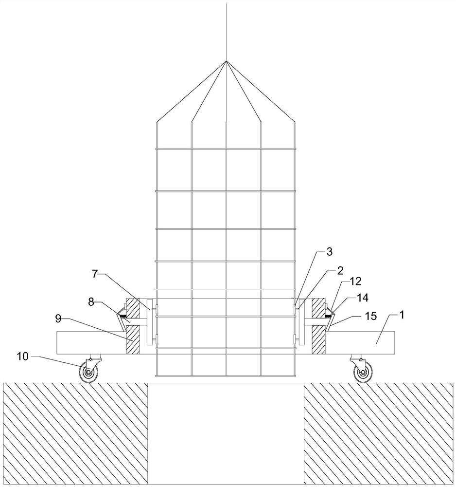
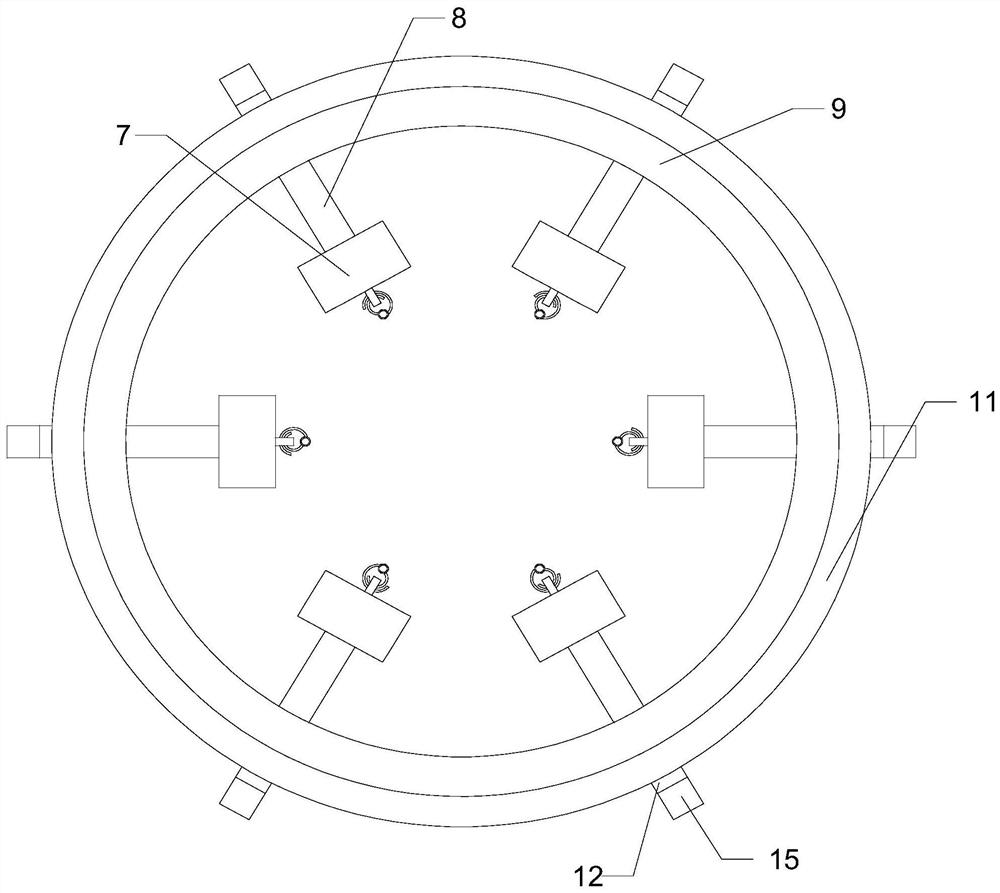
[0033] Such as Figure 1-8 As shown, this embodiment includes a sleeve I9, a plurality of bearing plates 1 are provided on the outer peripheral wall of the sleeve I9 ​​along the circumferential direction of the sleeve I9, There are a plurality of vertical plates 7 on the inner wall of the vertical plate 7, and a rectangular groove I17 is opened on the side wall of each vertical plate 7 away from the sleeve I9, and a rectangular groove I17 is provided on the bottom of the rectangular groove I17 along the axial direction of the sleeve I9. There are two baffles 23, and the upper and lower ends of each baffle 23 are provided with ribs 20 with a semicircular cross section, and the arc-shaped surface of each rib 20 is opposite to the inner wall of the rectangular groove I17 , arc-shaped slots I are provided on the arc-shaped surfaces of the upper and lower ends of each rib 20 along the horizontal direction, and rectangular slots II are provided on the two side walls of each baffle p...

Embodiment 2

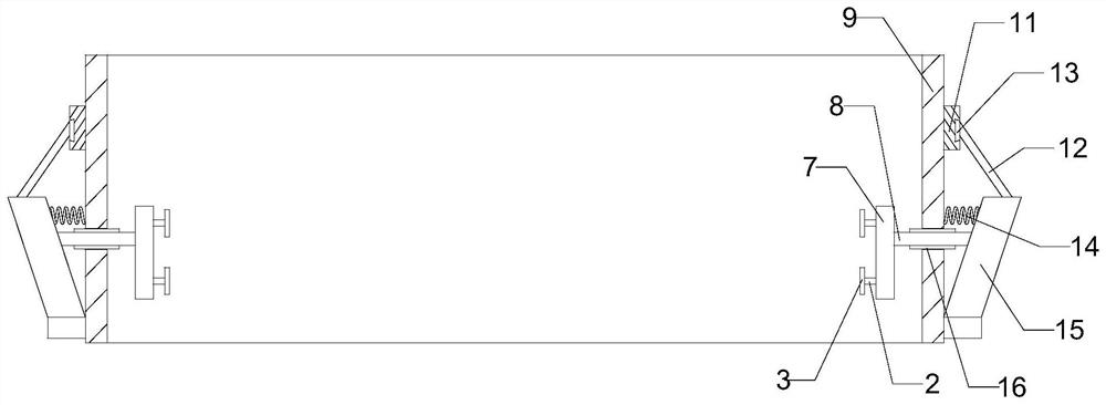
[0036] Such as Figure 1-8 As shown, this embodiment makes the following further limitations on the basis of Embodiment 1: This embodiment includes a plurality of limit rings I27 in the clamping assembly, and the groove bottom of the slider 21 away from the rectangular groove I17 There is a through hole I on the end surface of the upper part, and a push rod 28 is movable in the through hole I, and both ends of the push rod 28 are movable through the through hole I and then protrude from the through hole I. 21 A sleeve II30 is provided on the end surface of the groove bottom away from the rectangular groove I17, and the sleeve II30 is coaxial with the through hole I, and a spring is arranged on the inner wall of the through hole I near the bottom of the rectangular groove I17. I37, a limit ring I27 is connected to the outer wall of the extension end of a push rod 28, the limit ring I27 is connected to the spring I37, and a rotating shaft 36 is provided to rotate in the sleeve I...

Embodiment 3

[0041] Such as Figure 1-8 As shown, this embodiment makes the following further limitations on the basis of Embodiment 1: In this embodiment, along the circumferential direction of the sleeve I9, on the outer wall of the sleeve I9, there are a plurality of vertical plates 7 corresponding to each other. There are through holes II in each through hole II, and a push rod 8 is movable in each through hole II. Along the circumferential direction of the sleeve I9, on the outer wall of the lower end of the sleeve I9, a plurality of limiters corresponding to the through holes II are hinged. The position plate 15 is provided with a spring II14 on the outer wall of each push rod 8, one end of the spring II14 is connected to the outer wall of the sleeve I9, and the other end of the spring II14 is connected to the side of the limit plate 15 One end of the push rod 8 is connected to the vertical plate 7, the other end of the push rod 8 is hinged to the side wall of the limit plate 15, and...


PUM


Abstract

The invention discloses a hoisting device for a prefabricated reinforcement cage. A plurality of bearing plates are arranged on the outer circumferential wall of a sleeve I in the circumferential direction of the sleeve I, a plurality of vertical plates are arranged on the inner wall of the sleeve I in the circumferential direction of the sleeve I, and a rectangular groove I is formed in the sidewall, deviating from the sleeve I, of each vertical plate; two baffles are arranged at the groove bottom of each rectangular groove I in the axial direction of the sleeve I, the two ends of each baffle are subjected to arc treatment, arc grooves I are formed in the end faces of the two ends of each baffle, and rectangular grooves II are formed in the two side walls of each baffle in the vertical direction; the two rectangular grooves II and the two arc-shaped grooves I communicates end to end to form an annular channel, cavities I are formed in the two ends of each baffle, a chain meshing witha corresponding gear I is movably arranged in each annular channel, the chains are connected end to end, and a sliding block is arranged on the outer circumferential wall of each chain; and a clamping assembly used for clamping a main reinforcement of the reinforcement cage is arranged on the end face, deviating from the groove bottom of the rectangular groove I, of each sliding block.

Description

technical field [0001] The invention relates to the field of building construction, in particular to a hoisting device for a prefabricated steel cage. Background technique [0002] Due to the complexity of the foundation in modern building construction, it is necessary to use concrete piles as foundation support. In the existing concrete column construction technology, the concrete pile and the prefabricated steel cage are constructed separately in the punching hole. The steps are to first level and harden the construction ground, and then position the pile position on the construction ground to build Pile hole, use the crane to put the steel cage into the pile hole; insert the pipe into the pile hole to pour the concrete pile, so that the concrete fills the pile hole section with the steel cage and forms a concrete pile; the concrete pile is removed after hardening The upper layer is inferior; use a crane to lift the steel pipe vertically and put it into the pile hole, and...

Claims


Application Information

Patent Timeline
IPC IPC(8): B66C13/08B66C1/10E02D7/00E02D5/34
CPCB66C13/085B66C1/10E02D7/00E02D5/34
Inventor 杨蒙蒙
Owner 湖北才汇投资咨询有限公司
Why Eureka
Try Eureka