
Engine Cylinder head cover

A technology for engine cylinders and cylinder head covers, which is applied in the direction of engine components, machines/engines, mechanical equipment, etc., and can solve problems such as easy blockage of crankcase ventilation system, high engine crankcase pressure, pollution of supercharger, intercooler, etc. , to avoid condensed water and oil emulsion, ensure normal operation, simple and reasonable structure

Pending Publication Date: 2021-03-19
GUANGXI YUCHAI MASCH CO LTD
View PDF0 Cites 0 Cited by
  • Summary
  • Abstract
  • Description
  • Claims
  • Application Information

AI Technical Summary

Problems solved by technology

When there is a lot of emulsified engine oil, it is easy to block the crankcase ventilation system, resulting in high pressure in the engine crankcase and oil leakage. At the same time, the oil emulsion will pollute the supercharger, intercooler, etc., affecting the normal operation of the engine.

Method used


Image

  • Engine Cylinder head cover
  • Engine Cylinder head cover
  • Engine Cylinder head cover

Examples


Embodiment Construction

[0017] The specific embodiments of the present invention will be described in detail below in conjunction with the accompanying drawings, but it should be understood that the protection scope of the present invention is not limited by the specific embodiments.

[0018] Unless expressly stated otherwise, throughout the specification and claims, the term "comprise" or variations thereof such as "includes" or "includes" and the like will be understood to include the stated elements or constituents, and not Other elements or other components are not excluded.

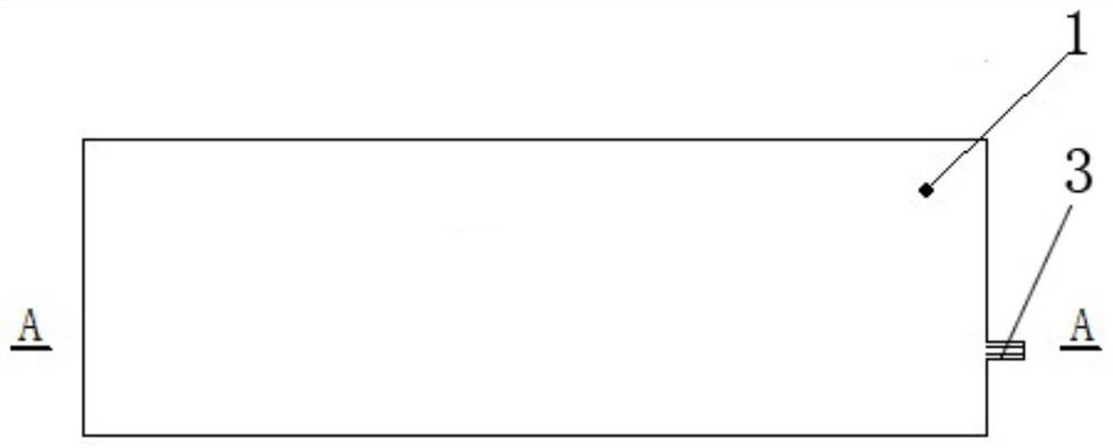
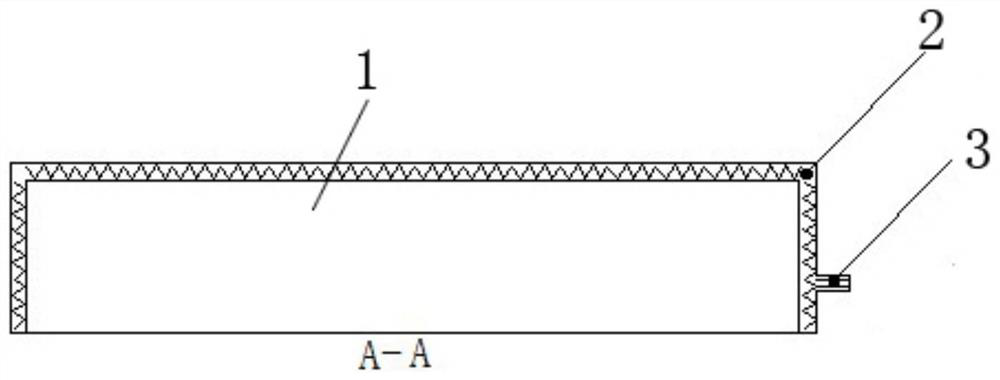
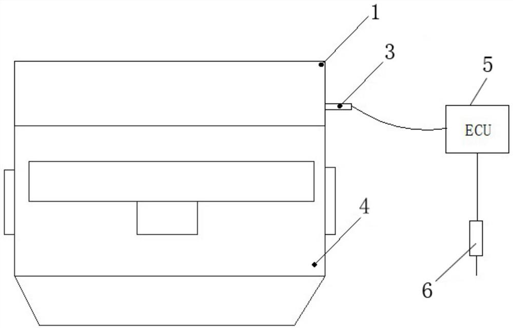
[0019] figure 1 It is a top structural schematic diagram of an engine cylinder head cover according to an embodiment of the present invention. figure 2 yes figure 1 Schematic diagram of the cross-sectional structure at A-A in the middle. image 3 It is a structural schematic view of an engine cylinder head cover installed on an engine according to an embodiment of the present invention.

[0020] Such as Figure 1 to F...


PUM


Abstract

The invention discloses an engine cylinder head cover. The engine cylinder head cover comprises a cylinder head cover body, electric heating mechanisms and a plug connector. The electric heating mechanisms are uniformly arranged in the peripheral wall surfaces of the cylinder head cover body. And the plug connector is arranged at one end of the cylinder head cover body, one end of the plug connector is electrically connected with the electric heating mechanisms, and the other end of the plug connector is electrically connected with an ECU, wherein the ECU can control the heating mechanisms tobe started and stopped. Therefore, the engine cylinder head cover has the advantages that the structure is simple and reasonable, and water vapor in an engine is prevented from generating condensate water and engine oil emulsion on the inner wall of the cylinder head cover, so that normal operation of an engine is guaranteed.

Description

technical field [0001] The invention relates to the technical field of engines, in particular to an engine cylinder head cover. Background technique [0002] The cylinder head cover of the engine is located on the top of the engine, and its main function is to prevent external impurities from entering the engine and play a role of sealing. Inside the cylinder head cover, engine rocker arms, valves, camshafts and other parts are running at high speed, during which a lot of oil particles and oil mist will be splashed on the cylinder head cover. [0003] When the engine is burning, some gas will leak out of the combustion chamber, and finally be discharged out of the engine through the oil pan, cylinder head cover, and breather. The current new emission regulations require that the crankcase ventilation be connected to the engine intake to avoid the emission of pollutants. The exhaust gas produced by engine combustion contains a small amount of water vapor, and if the fuel is ...

Claims


Application Information

Patent Timeline
IPC IPC(8): F02F7/00F01M13/04
CPCF01M13/04F01M2013/0472F02F7/0068
Inventor 赵福鑫伍平铅曾庆龙唐鹏程邓建林
Owner GUANGXI YUCHAI MASCH CO LTD
Learn More