
Transition device for optical module aging test, optical module aging device and method

An optical module testing and switching device technology, applied in the field of optical communication, can solve problems such as large voltage drop of power supply lines, impact of power supply equipment, damage to chips inside optical modules, etc., so as to eliminate excessive or low power supply and avoid surges. The effect of impact and elimination of sparking phenomenon

Active Publication Date: 2021-06-08
SONT TECH (SHEN ZHEN) LTD +1
View PDF0 Cites 0 Cited by
  • Summary
  • Abstract
  • Description
  • Claims
  • Application Information

AI Technical Summary

Problems solved by technology

[0003] For the traditional optical module burn-in board, after plugging in the power connector and turning on the mechanical switch, all the optical modules on a burn-in board are powered on at the same time at the same time, because there is a surge current in the pluggable optical module (although there is a slow start circuit inside the optical module, It can only slow down the inrush current to a certain extent, but it cannot completely eliminate it), the inrush current of so many optical modules stacked together will cause a great impact on the power supply equipment, and because multiple optical modules are connected at the same time At the instant of power on, the voltage drop on the power line is too large, which will cause the optical module to fail to obtain a suitable power supply voltage, which will cause damage to the internal chip of the optical module. After the aging is over, switch the mechanical switch to the off state. At this time, all The optical module is powered off at the same time. According to U=-L*(di / dt), a huge reverse impulse voltage will be generated at this time. Even if some high-end power supplies have better surge suppression circuits, it is difficult to Can withstand the frequent impact of surge current, not to mention that some power equipment itself has weak anti-surge capability, coupled with the increasing power consumption of optical modules, the surge current of individual optical modules when they are powered on / off It also increases significantly, which exacerbates the destructive impact. Furthermore, when the mechanical switch is opened and closed, due to the instantaneous high voltage, an arc will be generated, resulting in a sparking phenomenon.
[0004] Another significant disadvantage of the traditional burn-in board solution is that it is impossible to ensure that the power supply voltage of each optical module is stable at 3.3v

Method used


Image

  • Transition device for optical module aging test, optical module aging device and method
  • Transition device for optical module aging test, optical module aging device and method
  • Transition device for optical module aging test, optical module aging device and method

Examples


Embodiment Construction

[0061] In order to better explain the present invention and facilitate understanding, the present invention will be described in detail below through specific embodiments in conjunction with the accompanying drawings.

[0062] In order to better understand the above technical solutions, the following will describe exemplary embodiments of the present invention in more detail with reference to the accompanying drawings. Although exemplary embodiments of the present invention are shown in the drawings, it should be understood that the invention may be embodied in various forms and should not be limited to the embodiments set forth herein. Rather, these embodiments are provided so that the present invention can be more clearly and thoroughly understood, and the scope of the present invention can be fully conveyed to those skilled in the art.

[0063] In the embodiment of the present invention, port, interface and terminal all refer to the interface of the circuit or the pin of th...


PUM


Abstract

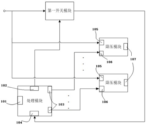
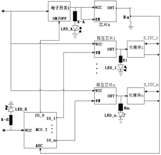
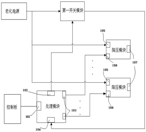
The present invention relates to an adapter device for optical module aging test, an optical module aging device and a method, wherein the adapter device is used to convert the voltage of the aging power supply to each optical module in several parallel optical modules. Corresponding to the power supply voltage, each optical module is powered on and communicated one by one according to the optical module test logic; wherein, the processing module sequentially enables each step-down module connected to the optical module according to the power-on signal of the switching device according to the optical module test logic , to realize the power-on of the optical modules one by one by the step-down modules; the processing module receives the test completion instruction of the control board, disconnects the first switch module to realize the power-off of the switching device, and turns off each step-down in turn according to the test logic of the optical module The voltage output port of the module to disconnect the optical modules one by one. The switching device of the present invention is applied to the aging test of the optical module, and can solve the problem of surge current when the existing optical module is powered on / off.

Description

technical field [0001] The invention relates to the technical field of optical communication, in particular to an adapter device for optical module aging test, an optical module aging device and a method. Background technique [0002] With the development and widespread use of optical communication technology, the stability and reliability of optical networks are more prominent. Since the quality of optical networks is largely affected by the quality of optical modules, during mass production, the optical modules must be Aging, early exposure of optical modules that will appear abnormal before the end of life. [0003] For the traditional optical module burn-in board, after plugging in the power connector and turning on the mechanical switch, all the optical modules on a burn-in board are powered on at the same time at the same time, because there is a surge current in the pluggable optical module (although there is a slow start circuit inside the optical module, It can onl...

Claims


Application Information

Patent Timeline
Patent Type & Authority Patents(China)
IPC IPC(8): G01R31/00
CPCG01R31/00
Inventor 蒋昌明李江华郑波孙鼎张伟魏志坚过开甲
Owner SONT TECH (SHEN ZHEN) LTD
Learn More