Double-lens time-division light-division light path and optical equipment

A time-splitting, dual-lens technology, applied in the AR field, can solve the problems of reduced reliability, large divergence angle, and high cost, and achieve the effects of improving projection brightness, reducing costs, and facilitating mass production

Pending Publication Date: 2021-03-19
深微光电科技(深圳)有限公司
View PDF2 Cites 0 Cited by
  • Summary
  • Abstract
  • Description
  • Claims
  • Application Information

AI Technical Summary

Problems solved by technology

[0003] At present, the existing solution in AR HUD is to use two display chips, one is DMD or LCOS, and the other is LCD. The two chips share part of the optical path to project scenes with different object distances; similar patents such as: CN109471262A, LCD display chip As a light source directly, the divergence angle is very large, and most of the light cannot be collected into the imaging system, resulting in a huge loss of brightness; at the same time, the use of two chips also increases the complexity of the circuit, resulting in a decrease in reliability, and the cost is relatively high. is also more expensive
[0004] In the field of 3D display, the polarization form is generally used, and the light of different polarization states enters the two lenses respectively through timing control, and finally the light overlaps on the screen to form a 3D effect; due to the use of polarization and liquid crystal modulators, its brightness is the least. More than half of the loss; similar patents such as: CN206193432U, the patent needs to use 3 kinds of modulation chips to modulate separately, plus complex modulation prism, its cost is high, the volume is large, and the mass production process is complicated

Method used


Image

  • Double-lens time-division light-division light path and optical equipment
  • Double-lens time-division light-division light path and optical equipment
  • Double-lens time-division light-division light path and optical equipment

Examples


Embodiment Construction

[0026] In order to make the purpose, technical solutions and advantages of the embodiments of the present invention clearer, a clear and complete description will be made below in conjunction with the technical solutions in the embodiments of the present invention. Obviously, the described embodiments are part of the embodiments of the present invention, and Not all examples. Based on the embodiments of the present invention, all other embodiments obtained by persons of ordinary skill in the art without making creative efforts belong to the protection scope of the present invention.

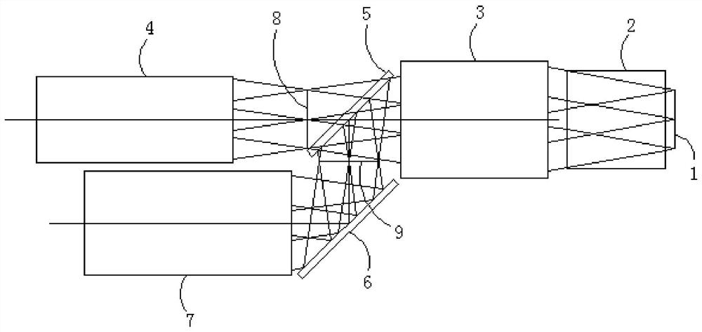
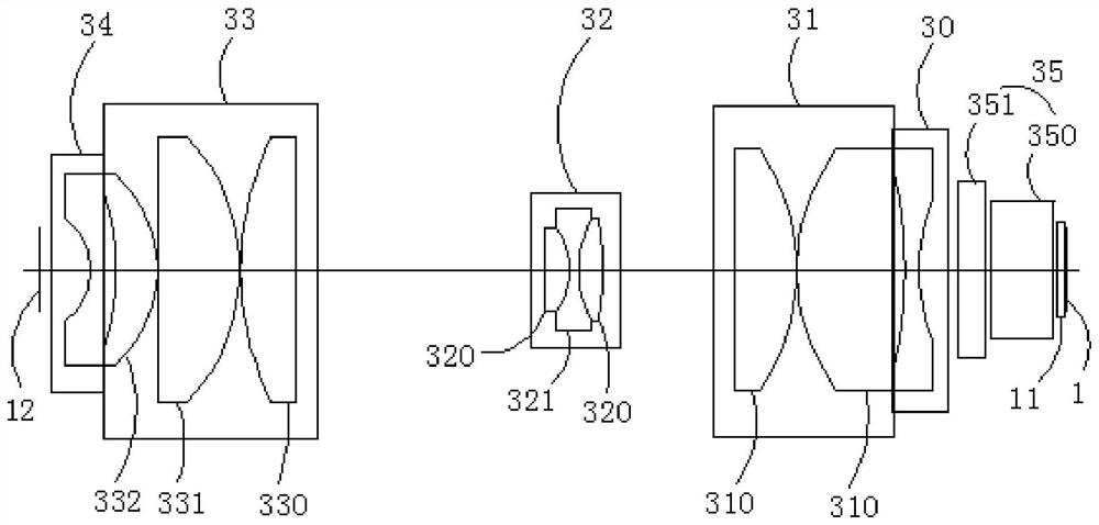
[0027] The dual-lens time-sharing optical path of the preferred embodiment of the present invention, such as figure 1 shown, see also Figure 2-6 , comprising a chip 1, a prism 2, an image transfer lens 3, a first lens 4, a beam splitting mirror 5, a steering mirror 6, a second lens 7 and a time-sharing switching device; the prism 2 is used to illuminate the light path of the chip 1 output beam ...


PUM


Abstract

The invention relates to a double-lens time-division light-division light path which comprises a chip, a prism, an image transferring lens, a first lens, a light-splitting reflector, a steering reflector, a second lens and a time-division switching device. The prism is used for separating an illumination light path from an imaging light path in an emergent light beam of the chip; the image transferring lens is an imaging lens and is used for converting the chip display area of the entity into a real image surface of the light path in the air; the first lens is used for imaging the real image surface again; the light-splitting reflector is used for reflecting the real image surface to form a light-splitting real image surface symmetrical about the reflecting surface, and the light-splittingreal image surface enters the second lens after passing through the steering reflector; the time-division switching device is used for moving the light splitting reflector so as to switch imaging onthe first lens and the second lens; through the time-division alternate display, the overlapping of two scenes is realized at the screen, an AR scene or a 3D scene is created, the final projection brightness can be improved, the cost of optical and electronic components is reduced by using a single chip, a polarization modulation light path is canceled, the size is small, and the volume productionis easy.

Description

technical field [0001] The present invention relates to the field of AR technology, and more specifically, to a dual-lens time-division optical path and optical equipment. Background technique [0002] In similar AR HUD and 3D projection displays, two different lenses are generally required to project different scene contents respectively, and finally overlapped together to produce the effect of virtual reality. [0003] At present, the existing solution in AR HUD is to use two display chips, one is DMD or LCOS, and the other is LCD. The two chips share part of the optical path to project scenes with different object distances; similar patents such as: CN109471262A, LCD display chip As a light source directly, the divergence angle is very large, and most of the light cannot be collected into the imaging system, resulting in a huge loss of brightness; at the same time, the use of two chips also increases the complexity of the circuit, resulting in a decrease in reliability, a...

Claims


Application Information

Patent Timeline
Patent Type & Authority Applications(China)
IPC IPC(8): G02B30/24G02B27/01G02B7/182G02B13/00
CPCG02B7/182G02B13/00G02B27/0101G02B2027/0134G02B30/24
Inventor 黄国豹黄万周张军黄金周徐壹游
Owner 深微光电科技(深圳)有限公司
Why Eureka
Try Eureka