Disk device

A disk-shaped, electrode-based technology, which is applied to the configuration/installation of circuit devices, circuit heating devices, and recording heads, and can solve problems such as changes in the quality of disk devices

Active Publication Date: 2021-03-19
KK TOSHIBA +1
View PDF16 Cites 0 Cited by
  • Summary
  • Abstract
  • Description
  • Claims
  • Application Information

AI Technical Summary

Problems solved by technology

However, due to the temperature of the solder and the vicinity of the solder when the terminals are connected by solder, the quality of the disk device may change.

Method used


Image

  • Disk device
  • Disk device
  • Disk device

Examples


no. 1 Embodiment approach

[0014] Below, refer to Figure 1 to Figure 5 The first embodiment will be described. In addition, in this specification, a component related to an embodiment and a description of the component may be described with plural expressions. The components and their descriptions are examples and are not limited by the expressions in this specification. A constituent element may be identified by a name different from the name in this specification. In addition, constituent elements may be described by expressions different from expressions in this specification.

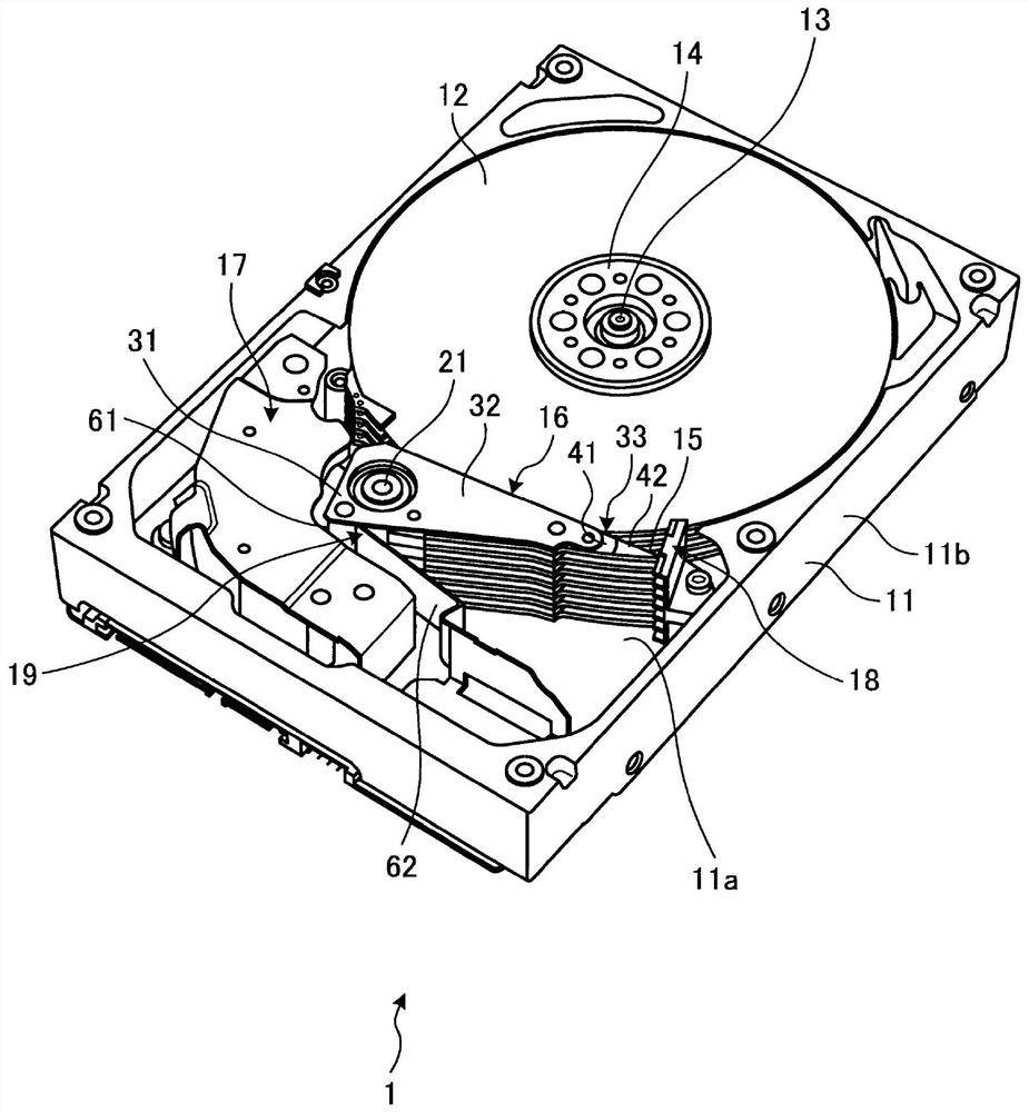
[0015] figure 1 It is an exemplary perspective view schematically showing the hard disk drive (HDD) 1 of the first embodiment. HDD1 is an example of a disk device. In addition, the disk device is not limited to the HDD1, and may be another disk device such as a hybrid hard disk drive.

[0016] Such as figure 1 As shown, HDD 1 has a housing 11, a plurality of magnetic disks 12, a spindle motor 13, clamping springs 14, ...

no. 2 Embodiment approach

[0120] Below, refer to Figure 6 A second embodiment will be described. In addition, in the description of the following embodiments, constituent elements having the same functions as already described constituent elements are assigned the same reference numerals as the already described constituent elements, and description thereof may be omitted. In addition, a plurality of constituent elements attached with the same reference numerals are not limited to common functions and properties, and may have different functions and properties corresponding to the respective embodiments.

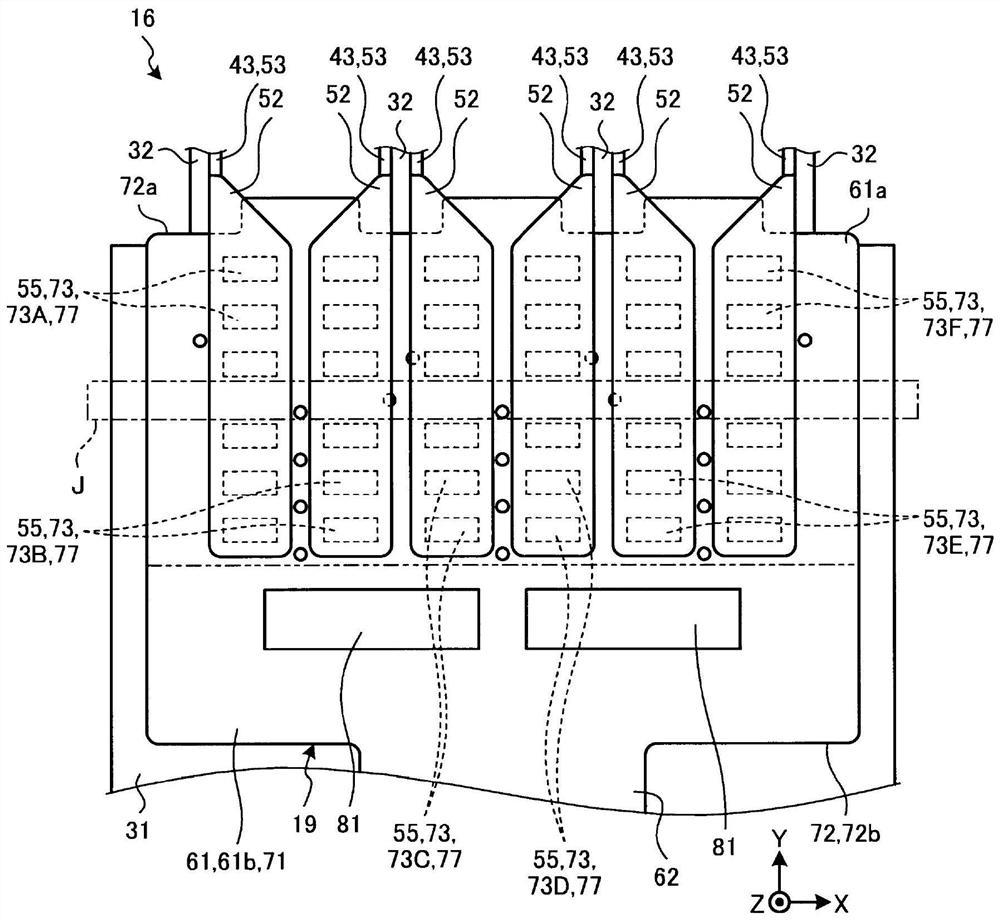
[0121] Figure 6 It is an exemplary plan view schematically showing a part of FPC 19 of the second embodiment. exist Figure 6 In , the second insulating layer 19d is omitted. Such as Figure 6 As shown, the plurality of pads 73 includes a plurality of inner pads 73i and a plurality of outer pads 73o. The inner pad 73i is an example of an inner terminal. The external pad 73o is an example of ...


PUM


Abstract

The embodiment provides a disk device capable of adjusting the temperature of a flexible printed circuit board at the time of connecting terminals. A disk device according to one embodiment includes arecording medium, a magnetic head, a wiring member, and a flexible printed circuit board. The magnetic head is configured to read / write information from / to the recording medium. The wiring member includes a plurality of first terminals, and a plurality of first wires that electrically connect the magnetic head to the first terminals. The flexible printed circuit board includes a surface, a plurality of second terminals located on the surface to be connected to the first terminals by means of a conductive adhesive, and a ground plane spaced apart from the second terminals in a direction alongthe surface.

Description

[0001] Associate application [0002] This application enjoys the priority of the basic application based on Japanese Patent Application No. 2019-170065 (filing date: September 19, 2019). This application incorporates the entire content of the basic application by referring to this basic application. technical field [0003] Embodiments of the present invention relate to disk devices. Background technique [0004] A disk device such as a hard disk drive (HDD) has a magnetic disk and a magnetic head for reading and writing information to the magnetic disk. For example, a flexible part, a flexible printed circuit board (FPC), electrically connects a control device controlling the HDD and a magnetic head. The terminals of the flexible member and the terminals of the FPC are connected to each other by, for example, solder. However, the quality of the disk device may change due to the temperature of the solder and the vicinity of the solder when the terminals are connected wit...

Claims


Application Information

Patent Timeline
IPC IPC(8): G11B5/48H05K1/02
CPCG11B5/4806H05K1/0201H05K1/0213G11B5/486G11B5/4846H05K1/118H05K2201/09409H05K1/0218H05K1/18G11B5/4853H01R12/61H05K1/116H01R4/04H01R2201/06H05K2201/09227
Inventor 佐藤佑树
Owner KK TOSHIBA
Why Eureka
Try Eureka