Shell assembly and motor using same

A shell component and component technology, which is applied in the direction of electric components, electromechanical devices, electrical components, etc., can solve the problems of small effective contact length between the motor shaft and the motor shell, low fixing strength between the motor shaft and the motor shell, etc., and achieve improved The effect of riveting fixing strength, large effective contact length, and reducing the amount of external expansion deformation

Active Publication Date: 2022-03-01
安徽雷利智能科技有限公司
View PDF5 Cites 0 Cited by
  • Summary
  • Abstract
  • Description
  • Claims
  • Application Information

AI Technical Summary

Problems solved by technology

[0004] In order to solve the technical problem that the effective contact length between the motor shaft and the motor casing is too small in the prior art, resulting in low fixing strength between the motor shaft and the motor casing, the present invention provides a casing assembly and a motor using it to solve the above question

Method used


Image

  • Shell assembly and motor using same
  • Shell assembly and motor using same
  • Shell assembly and motor using same

Examples


Embodiment 1

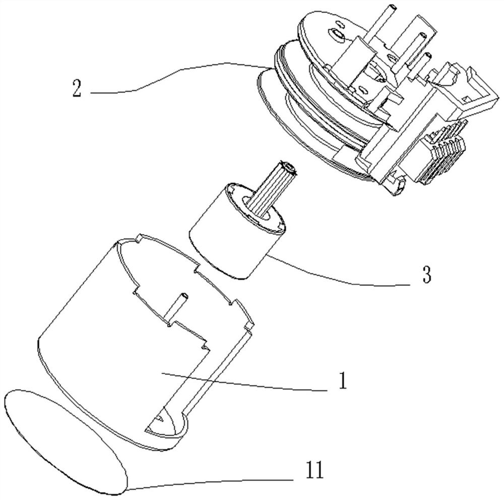
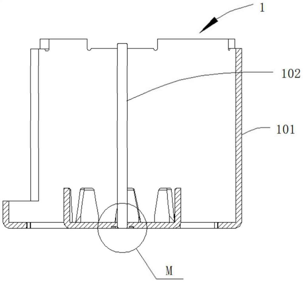
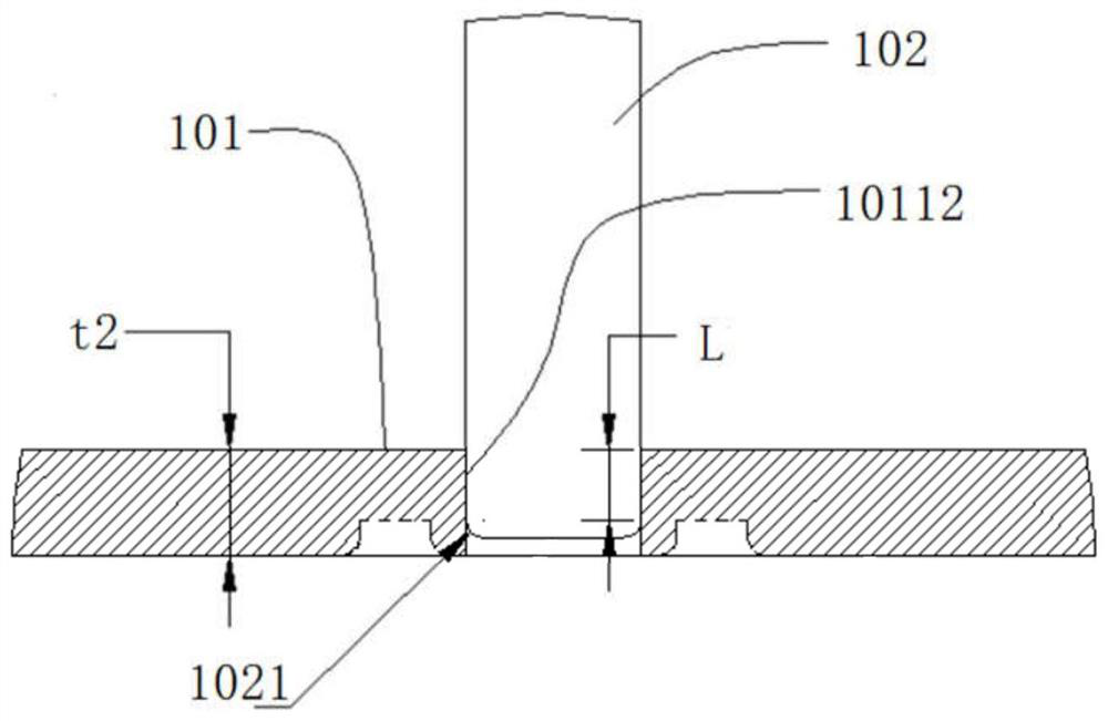
[0037] Example 1, such as Figure 4-Figure 7 As shown, a housing assembly includes a motor housing 101 and a motor shaft 102. The motor housing 101 is composed of a bottom plate 1011 and a side wall 1012 surrounding the bottom plate 1011 to form a barrel-shaped structure with an open end. The inside of the barrel-shaped structure A cavity is formed, the area where the cavity is located is the inside of the motor housing 101 or the side wall 1012, one end of the motor shaft 102 is provided with a chamfer 1021, and the center of the bottom plate 1011 protrudes toward the opening end of the motor housing 101 to form a step 10111, There is a shaft hole 10112 in the center of the step 10111, and one end of the motor shaft 102 provided with a chamfer 1021 is suitable for being inserted into the shaft hole 10112. The thickness t1 of the step is equal to the thickness t2 of the bottom plate.

[0038] The side wall 1012 extends upward from one side of the bottom plate 1011, and the sid...

Embodiment 2

[0045] Embodiment 2, on the basis of Embodiment 1, there is a first annular decompression groove 1013 at the junction of the bottom plate 1011 and the side wall 1012. Such as Figure 6 and Figure 10 As shown, the first annular decompression groove 1013 is located at the root of the side wall 1012, adhering to the inner wall of the side wall 1012, and the cross section of the first annular decompression groove 1013 is approximately rectangular. The principle of this design is: the sheet material 7 forms the side wall 1012 through the stretching process and the shaping process, and the stretching process is realized by the stretching die, including the stretching die 8a and the stretching punch 8b, in order to prevent the stretching process When the side wall 1012 is stretched and torn, a punch fillet transition area will be provided at the front end of the stretching punch 8b, and a transition fillet area 9 will be formed at the root of the side wall 1012. There is a certain...

Embodiment 3

[0046] Embodiment 3, on the basis of Embodiment 1 or Embodiment 2, a first decompression groove 1014 is provided at the junction of the bottom plate 1011 and the pole claw 10113 . Such as Figure 6 As shown, the structure of the first decompression groove 1014 is similar to that of the first annular decompression groove 1013, and the effect is the same. The difference from the first annular decompression groove 1013 is that the first decompression groove 1014 is the The corresponding number of arc slots.

[0047] The principle of setting the first decompression groove 1014 is: the material of the motor housing 101 is free-cutting steel, because the bending part of the pole claw 10113 has a certain internal stress, and the material itself has a certain elasticity, so punching and bending Afterwards, there will be a certain rebound, and at this time, the verticality between the pole claw 10113 and the bottom plate 1011 cannot be guaranteed; therefore, along the root of the pole...


PUM


Abstract

The invention discloses a shell assembly and a motor using it, comprising a motor shell and a motor shaft, the motor shell is composed of a bottom plate and side walls surrounding the bottom plate to form a barrel structure with one end open, the motor One end of the shaft is provided with a chamfer, and the center of the bottom plate protrudes toward the opening end of the motor housing to form a step, and the center of the step has a shaft hole, and the end of the motor shaft provided with a chamfer is suitable for inserted into the shaft hole; the thickness t1 of the step is equal to the thickness t2 of the bottom plate. In the case assembly and the motor using it according to the present invention, a raised step is provided at the center of the bottom plate, and the thickness t1 of the step is equal to the thickness t2 of the bottom plate, so that when the motor shaft is matched with the shaft hole, the step A chamfer transition area can be reserved between the lower surface and the lower surface of the bottom plate, so as to ensure that after the motor shaft and the motor housing are riveted, the effective contact length is increased, and the riveted fixing strength of the motor shaft and the motor housing is improved.

Description

technical field [0001] The invention relates to the technical field of motors, in particular to a housing assembly and a motor using the same. Background technique [0002] Motors are widely used in household appliances. Such as figure 1 As shown, the main features of a general motor include a housing assembly 1, a rotor assembly 3, a stator assembly 2, a nameplate 11, and the like. Such as figure 2 As shown, the housing assembly 1 is composed of a motor housing 101 and a motor shaft 102; the motor housing has a shaft hole 10112, and the motor shaft 102 is riveted and fixed in the shaft hole of the motor housing 101; the motor shaft 102 is used to fix the rotor assembly 3 ; [0003] In the motor of the prior art, the bottom of the motor housing 101 is a planar structure, and the shaft hole 10112 of the motor housing 101 is on the bottom plane of the motor housing 101, such as image 3 shown. Since the nameplate needs to be adhered to the bottom of the motor case, afte...

Claims


Application Information

Patent Timeline
Patent Type & Authority Patents(China)
IPC IPC(8): H02K5/04
CPCH02K5/04
Inventor 刘金俊罗明
Owner 安徽雷利智能科技有限公司
Why Eureka
Try Eureka