Supercharge Your Innovation With Domain-Expert AI Agents!

Hair cutting appliance

一种毛发切割、器具的技术,应用在金属加工等方向,能够解决影响切割单元机械工作切割系统寿命等问题,达到优化切割性能或磨损和能量损失、避免摩擦力的变化的效果

Active Publication Date: 2021-03-19
KONINKLIJKE PHILIPS NV
View PDF11 Cites 0 Cited by
  • Summary
  • Abstract
  • Description
  • Claims
  • Application Information

AI Technical Summary

Problems solved by technology

Also, this situation can negatively affect the mechanical work of the cutting unit, the control of the beard cutting process and the life of the cutting system

Method used


Image

  • Hair cutting appliance
  • Hair cutting appliance
  • Hair cutting appliance

Examples


Embodiment Construction

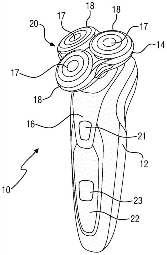
[0065] figure 1 A perspective top view of a hair cutting device 10 configured as a shaver is shown. The hair cutting device 10 comprises an elongated main housing 12 and a hair cutting appliance configured as a shaving unit 20 arranged at a top end of the main housing 12 . The shaving unit 20 comprises a cutting head 14 with three cutting units 17 arranged in a somewhat triangular fashion.

[0066] In the main housing 12, a driver 16 (not shown in detail here) is accommodated. The drive 16 is configured to operate and actuate the shaving unit 20 by means of at least one drive spindle, which will be explained below with reference to the following figures. At the main housing 12, other components of the hair cutting device 10 may be provided, such as operator controls, an on-off switch 21, external setting pads 23, batteries, sockets for cables etc.

[0067] The shaving unit 20 is altogether removable from the hair cutting device 10 comprising the main housing 12, the drive 1...


PUM


Abstract

A hair cutting appliance comprises an external cutting member and an internal cutting member arranged rotatable to the external cutting member for cutting hair. The internal cutting member is driven via a first coupling element by a drive spindle (24) rotatable about an axis of rotation (35) and having a first spindle part (26) arranged to be driven by a drive, and a second spindle part (30) arranged to be coupled to the internal cutting member, the first and second spindle parts (26, 30) being displaceable relative to each other in an axial direction parallel to the axis of rotation (35); wherein the second spindle part (30) comprises a second coupling element (34) which is coupled to the first coupling element for transmitting, during operation, a driving torque about the axis of rotation (35) from the drive spindle (24, 24a) to the internal cutting member; wherein one of the first and second spindle parts (26, 30) comprises an abutment element (36) and the other of the first and second spindle parts (26, 30) comprises an abutment surface (38) arranged to cooperate with the abutment element (36) for transmitting, during operation, the driving torque from the first spindle part (26) to the second spindle part (30); wherein the abutment surface (38) is arranged at an angle alpha relative to a tangential direction relative to the axis of rotation (35), wherein 0 degree<alpha<90degrees such that a transmission of the driving torque from the first spindle part (26) to the second spindle part (30) via the abutment element (36) and the abutment surface (38) results in a force exerted by the first spindle part (26) on the second spindle part (28) having a component parallel to the axis of rotation (35) and directed towards the internal cutting member, wherein the first and second coupling elements are configured to transmit the component from the second spindle part (30) to the second coupling element (34).

Description

technical field [0001] The present invention relates to a hair cutting device that can be used as a shaver or a hair trimmer. Background technique [0002] Rotary electric shavers typically use a coupled spindle to transfer rotational power from the drive to the cutting system. Besides that, there are some secondary functions, one of which is to apply axial force to the cutting element. This is the closing force by which the cutting element is held on the shaving guard. A closing force that is too low results in a cutting gap between the cutting element and the shaving guard, whereby incorrect cutting and hair pulling occur. On the other hand, increasing the closing force also increases friction, thereby causing noise, wear, energy loss, and thus shortening battery life. Coupling spindles are generally designed to employ a substantially constant axial force (cutting preload) that remains within a functionally acceptable operating range. [0003] From US 5,283,953 is know...

Claims


Application Information

Patent Timeline
Patent Type & Authority Applications(China)
IPC IPC(8): B26B19/14B26B19/28
CPCB26B19/14B26B19/28B26B19/145
Inventor D·霍罗威茨M·C·彼得利I·伯斯玛
Owner KONINKLIJKE PHILIPS NV
Features
  • R&D
  • Intellectual Property
  • Life Sciences
  • Materials
  • Tech Scout
  • Unparalleled Data Quality
  • Higher Quality Content
  • 60% Fewer Hallucinations
Learn More