
Hydraulic clamp with bidirectional clamping effect

A technology for hydraulic clamps and base plates, applied in the field of hydraulic clamps, can solve problems such as wear and damage of clamping arms, and achieve the effects of improving service life, reducing use costs and avoiding wear and tear.

Pending Publication Date: 2021-03-23
广州皖安机电设备有限公司
View PDF4 Cites 8 Cited by
  • Summary
  • Abstract
  • Description
  • Claims
  • Application Information

AI Technical Summary

Problems solved by technology

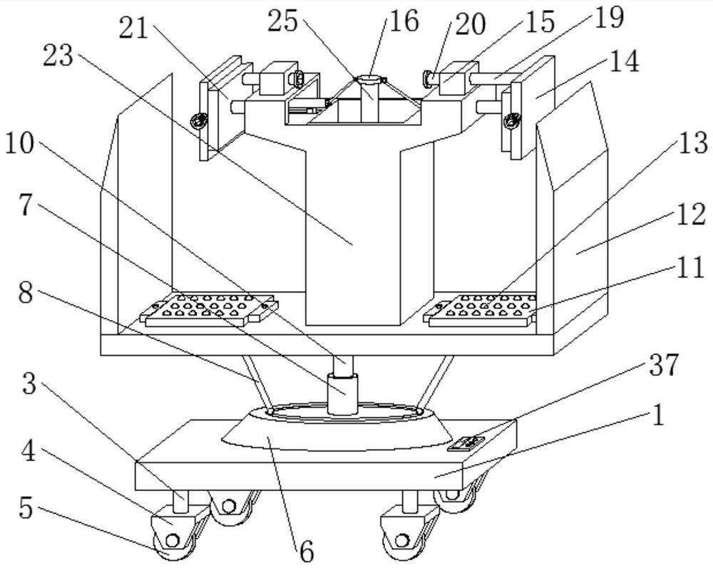
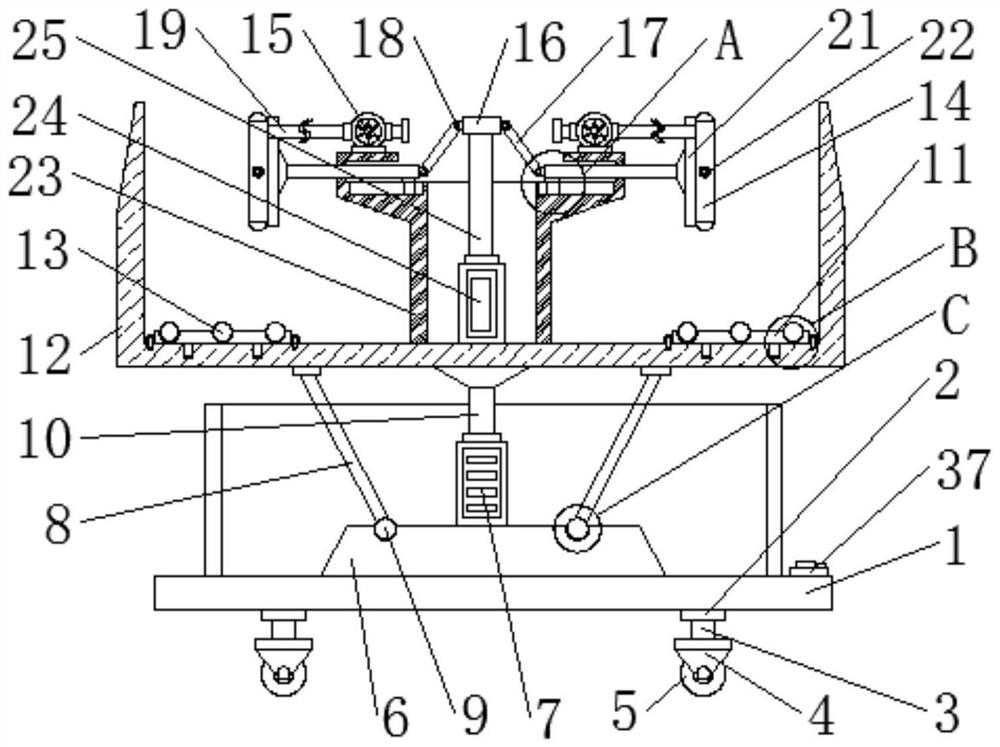
[0006] The purpose of the present invention is to provide a clamping arm with a two-way clamping effect in order to solve the problem that the clamping arm will use excessive force to clamp the workpiece, which will easily cause damage to the clamping arm and wear when the workpiece is moved on the rack. hydraulic fixture

Method used


Image

  • Hydraulic clamp with bidirectional clamping effect
  • Hydraulic clamp with bidirectional clamping effect
  • Hydraulic clamp with bidirectional clamping effect

Examples


Embodiment Construction

[0027] The following will clearly and completely describe the technical solutions in the embodiments of the present invention with reference to the accompanying drawings in the embodiments of the present invention. Obviously, the described embodiments are only some, not all, embodiments of the present invention. Based on the embodiments of the present invention, all other embodiments obtained by persons of ordinary skill in the art without making creative efforts belong to the protection scope of the present invention.

[0028] In the description of the present invention, it should be noted that the terms "center", "upper", "lower", "left", "right", "vertical", "horizontal", "inner", "outer" etc. The indicated orientation or positional relationship is based on the orientation or positional relationship shown in the drawings, and is only for the convenience of describing the present invention and simplifying the description, rather than indicating or implying that the referred d...


PUM


Abstract

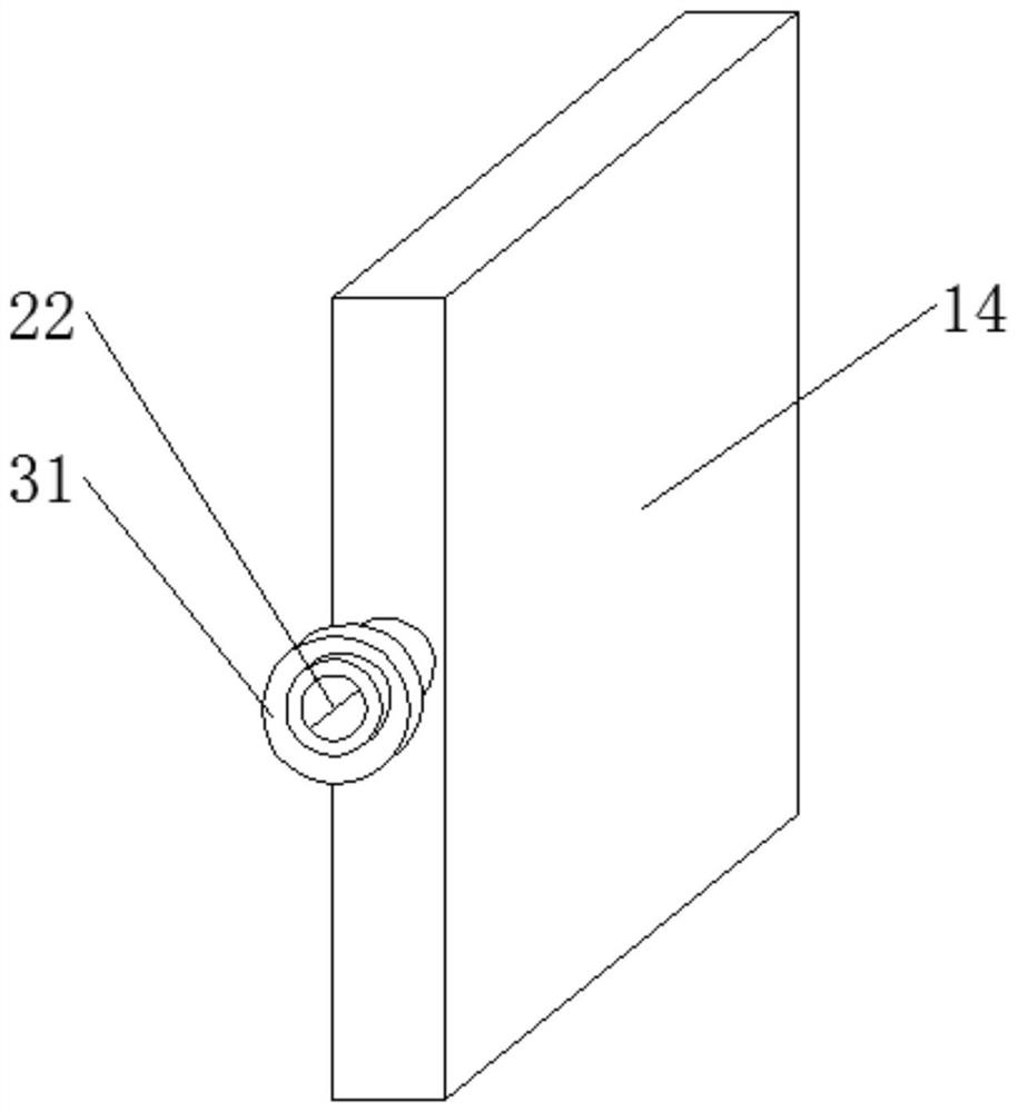
The invention discloses a hydraulic clamp with a bidirectional clamping effect, and relates to the field of hydraulic clamps. The hydraulic clamp comprises a bottom plate, a support seat is fixed at the top of the bottom plate, and a motor is mounted in the middle of the top of the support seat. Through the arrangement of an air exhauster, air inlet pipes, air outlet hoses, buffering air bags, airvalves and exhaust pipes, after a user places a workpiece on a placement frame, the user starts the air exhauster through an operation table, the air exhauster works to enable the air inlet pipes toexhaust air, air enters the buffering air bags through the air outlet hoses to inflate the buffering air bags, after inflation is completed, the user can start an air cylinder to enable a piston rod to extend, then movable rods can be driven to move, clamping plates and the buffering air bags are also driven to move, the buffering air bags move to enable the clamping plates to clamp the workpiece,while when the air cylinder works to enable the piston rod to continue to retract and enable the movable rods to move to apply pressure to the workpiece, the buffering air bags are stressed to be compressed, and therefore, a buffering effect can be achieved on the movable rods and connecting rods.

Description

technical field [0001] The invention relates to the field of hydraulic clamps, in particular to a hydraulic clamp with bidirectional clamping effect. Background technique [0002] A fixture is a device used to fix the processing object in the process of mechanical manufacturing so that it can occupy the correct position to accept construction or testing, also known as a fixture; in a broad sense, any process in the process is used to quickly and conveniently , The device for safely installing the workpiece can be called a fixture, such as welding fixtures, inspection fixtures, assembly fixtures, machine tool fixtures, etc. Among them, machine tool fixtures are the most common, often referred to as fixtures. When processing a workpiece on a machine tool, in order to make the surface of the workpiece meet the technical requirements such as the size, geometric shape, and mutual position accuracy with other surfaces specified in the drawing, the workpiece must be installed (pos...

Claims


Application Information

Patent Timeline
Patent Type & Authority Applications(China)
IPC IPC(8): B25B11/00B25H1/10B25H5/00
CPCB25B11/00B25H1/10B25H5/00
Inventor 秦臻
Owner 广州皖安机电设备有限公司
Learn More