Web-fed material printing equipment with adjustable width of plate with shaft

A technology of printing equipment and roll, which is applied in the field of roll material printing equipment, can solve the problems of ink tank ink leakage, high investment cost, and influence on the stability of the plate roll, so as to improve the firmness, reduce the input cost, and ensure the rotation of the plate roll Highly stable effect

Active Publication Date: 2021-03-23
黄山枘淼机电科技有限公司
View PDF14 Cites 0 Cited by
  • Summary
  • Abstract
  • Description
  • Claims
  • Application Information

AI Technical Summary

Problems solved by technology

[0003] When the roll material is printed, the corresponding wide-width version roller is usually selected according to the width of the printing object, and these different-width version rollers will be combined with the printing equipment corresponding to the wide-width movable model, and a single model supports The width of the tape shaft plate is limited, and the length range of the tape shaft plate width is too large, which affects the stability of the plate roll rotation and the printing quality of the product. Therefore, for enterprises, the investment cost

Method used


Image

  • Web-fed material printing equipment with adjustable width of plate with shaft
  • Web-fed material printing equipment with adjustable width of plate with shaft
  • Web-fed material printing equipment with adjustable width of plate with shaft

Examples


Embodiment Construction

[0036] The technical solutions in the embodiments of the present invention will be clearly and completely described below in conjunction with the embodiments of the present invention. Apparently, the described embodiments are only some of the embodiments of the present invention, not all of them. Based on the embodiments of the present invention, all other embodiments obtained by persons of ordinary skill in the art without creative efforts fall within the protection scope of the present invention.

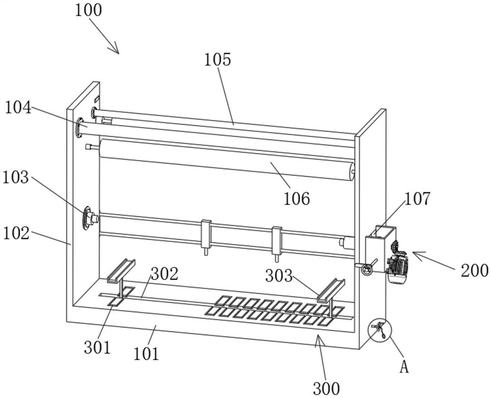
[0037] see Figure 1-12 As shown, a roll material printing device with adjustable width of the belt shaft includes a printing machine frame 100. The printing machine frame 100 includes a bottom plate 101, and vertical plates 102 are fixed on both sides of the top surface of the bottom plate 101, wherein one vertical plate The middle part of the plate 102 is rotatably connected with a driven top shaft 103, and the middle part of the other vertical plate 102 is provided with a squar...


PUM


Abstract

The invention relates to the technical field of printing equipment, and particularly relates to web-fed material printing equipment with the adjustable width of a plate with a shaft. The equipment comprises a printing rack, the printing rack comprises a bottom plate, vertical plates are fixed on two sides of the top surface of the bottom plate, the middle part of one vertical plate is rotatably connected with a driven ejector shaft, the middle part of the other vertical plate is provided with a square hole, a main transverse rod and an auxiliary transverse rod are fixed between the upper portions of the inner side walls of the two vertical plates, conveying rollers are rotatably connected to the positions, located on the lower portion of the main transverse rod, of the inner side walls ofthe two vertical plates, and an ink fountain fixing mechanism used for bearing an ink fountain is arranged on the top face of the bottom plate. According to the web-fed material printing equipment, after a first nut block moves relatively, a driving rod can be driven to push an ejector shaft fixing frame to move along a sliding rail, and compared with the mode that the driven ejector shaft is changed to fix plate cylinders, the structure is higher in plate cylinder rotating stability, therefore, the fixing firmness of the printing equipment on the plate cylinders with different plate widths isimproved, and the investment cost of the equipment of enterprises is reduced.

Description

technical field [0001] The invention relates to the technical field of printing equipment, in particular to a roll material printing equipment with adjustable tape shaft plate width. Background technique [0002] Web printing equipment is a machine that uses gravure printing. The graphic part of the printing plate is concave, and the blank part is on the same plane as the outer circle of the printing plate cylinder. When the roll material printing equipment prints, the entire plate cylinder is inked, and the ink on the blank part of the plate is scraped off with a scraper, leaving the ink on the graphic part, and then passed through the paper, and the impression cylinder is pressed on the back of the paper. Printing, so that the ink in the concave part is directly transferred to the paper surface, and finally the printed matter is piled up or rewound through the receiving part. [0003] When the roll material is printed, the corresponding wide-width version roller is usual...

Claims


Application Information

Patent Timeline
IPC IPC(8): B41F9/00B41F9/06
CPCB41F9/003B41F9/061B41F9/06
Inventor 谢俊武姚雷吕挺
Owner 黄山枘淼机电科技有限公司
Why Eureka
Try Eureka