
Rail hoisting structure and suspension type rail transit system

A technology of rail cranes and rails, which is applied to the elevated railway systems, tracks, roads and other directions using suspended vehicles, can solve the problems that the tracks are prone to torsion and have potential safety hazards, and achieve the effect of reducing potential safety hazards.

Active Publication Date: 2021-03-23
CRRC TANGSHAN CO LTD
View PDF11 Cites 0 Cited by
  • Summary
  • Abstract
  • Description
  • Claims
  • Application Information

AI Technical Summary

Problems solved by technology

[0005] In the embodiment of the present application, a rail hoisting structure and a suspended rail transit system are provided, which are mainly used to solve the problem that the rail is prone to torsion and has potential safety hazards in related technologies

Method used


Image

  • Rail hoisting structure and suspension type rail transit system
  • Rail hoisting structure and suspension type rail transit system
  • Rail hoisting structure and suspension type rail transit system

Examples


Embodiment 1

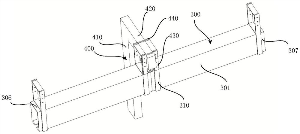
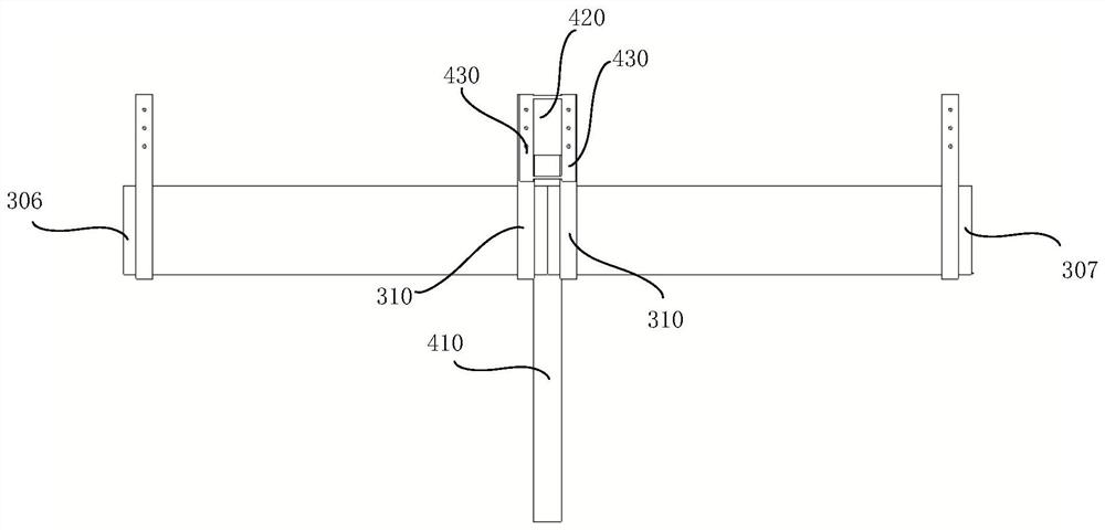
[0044] figure 2 Shown in is a schematic diagram of the rail hoisting structure provided by an embodiment of the present application; image 3 shown in figure 2 A schematic diagram of the main view structure; Figure 4 Shown in is a schematic structural diagram of the track provided by an embodiment of the present application; Figure 5 Shown in is a schematic structural diagram of the first fixing device provided by an embodiment of the present application; Image 6 Shown in is a schematic structural diagram of a supporting device provided by an embodiment of the present application; please refer to Figure 2-Figure 6 .

[0045] This embodiment provides a rail hoisting structure, including a rail 300 and a supporting device 400, wherein the rail 300 is used to provide a running path for a rail vehicle, so that the rail vehicle can move along the rail 300; The fixed support is in the space above the ground to relieve the pressure of ground transportation.

[0046] Optio...

Embodiment 2

[0068] This embodiment provides a suspended rail transit system, including a rail vehicle and the rail hoisting structure described in Embodiment 1 above.

[0069] Specifically, the rail vehicle can be connected to the running device arranged inside the track through the hanging device passing through the opening, and the running device can drive the rail vehicle to move along the track. The rail transit system also includes structures such as dispatching rooms and platforms scattered around the track.

[0070] Since the suspended rail transit system of this embodiment adopts the rail hoisting structure of the above-mentioned embodiment 1, the rail is less likely to be twisted during operation, and the safety is better.


PUM


Abstract

The embodiment of the invention provides a rail hoisting structure and a suspension type rail transit system. The rail hoisting structure comprises a rail and a supporting device, wherein the rail comprises a first side face and a second side face which are oppositely arranged, and a first fixing device is arranged on the rail; the first fixing device comprises a first fixing plate arranged outside the first side face and a second fixing plate arranged outside the second side face. The supporting device comprises a stand column and a cantilever, the axis of the cantilever is orthogonal to theaxis of the rail, the stand column is used for fixing the cantilever to the ground, a second fixing device is arranged on the side, away from the stand column, of the cantilever and comprises a thirdfixing plate and a fourth fixing plate which are located on the same side face of the cantilever, and the third fixing plate and the fourth fixing plate are oppositely arranged; the first fixing plateis fixedly connected with the third fixing plate, and the second fixing plate is fixedly connected with the fourth fixing plate. The rail hoisting structure is advantaged in that the track is not prone to torsion, and potential safety hazards are reduced.

Description

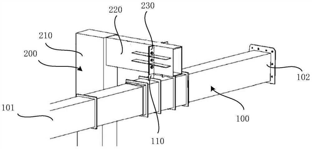
technical field [0001] The application relates to rail vehicle manufacturing technology, in particular to a rail hoisting structure and a suspended rail transit system. Background technique [0002] Rail transit system refers to a type of transportation system in which vehicles need to travel on specific tracks. Common rail transit systems include railway systems, subway systems, light rail systems, tram systems, and maglev rail systems. In the above different types of rail transit systems, the tracks are all set on the ground, and with the increasing traffic congestion on the ground, the suspended rail transit system has emerged as the times require. The suspended rail transit system suspends the rails and rail vehicles in the high-altitude space above the ground, thereby making full use of the space above the ground and helping to relieve the traffic pressure on the ground. [0003] figure 1 Shown in is a simplified diagram of the track hoisting structure in the related...

Claims


Application Information

Patent Timeline
IPC IPC(8): E01B25/22E01B25/24B61B3/00B61B12/00
CPCE01B25/22E01B25/24B61B3/00B61B12/00
Inventor 王冬卫许红梅许瑾赵峰王艳荣徐晖
Owner CRRC TANGSHAN CO LTD
Learn More