Concrete pouring chute for deep foundation pit

A technology for concrete and deep foundation pits, which is used in construction, building construction, infrastructure engineering, etc., can solve problems such as interruption of concrete pouring, cold joints, faults, and inability to continuously pour concrete, and achieve the effect of ensuring construction quality.

Pending Publication Date: 2021-03-23
NO 5 ENG CO LTD OF CCCC FIRST HARBOR ENG
0 Cites 0 Cited by

AI-Extracted Technical Summary

Problems solved by technology

When the pumping equipment breaks down and cannot be repaired in time, the concrete pouring construction will be interrupted, and...

Method used

[0019] The present invention utilizes shaped steel as the primary chute 4, and the light wood structure as the secondary chute 5. The two-stage chutes are connected ...

Abstract

The invention discloses a concrete pouring chute for a deep foundation pit. The concrete pouring chute for the deep foundation pit comprises an enclosure structure steel sheet pile, and further comprises a first-stage chute body and a second-stage chute body. The first-stage chute body is connected with the enclosure structure steel sheet pile through a clamping ring, the first-stage chute body can rotate up and down along the connecting position of the clamping ring, the second-stage chute body is connected with the first-stage chute body through a rotating shaft assembly, and the second-stage chute body can rotate by 360 degrees along the horizontal plane of the connecting position. According to the concrete pouring chute for the deep foundation pit, the first-stage chute body and the second-stage chute body which rotate in a graded mode are used in cooperation, continuous construction of concrete can be guaranteed, and the concrete pouring construction quality is guaranteed.

Application Domain

Foundation engineeringBuilding material handling

Technology Topic

Steel platesStructural engineering +3

Image

  • Concrete pouring chute for deep foundation pit
  • Concrete pouring chute for deep foundation pit

Examples

  • Experimental program(1)

Example Embodiment

[0014] In order to make the objects, technical solutions, and advantages of the present invention, the present invention will be described in further detail below. It should be understood, however,, however, as used herein is intended to explain the invention, and is not intended to limit the scope of the invention.
[0015] Unless otherwise defined, all technical terms and scientific terms used herein are generally understood by those skilled in the art of the present invention, and the terms used in the specification of the present invention are intended to describe specific implementation purposes only. The purpose of the example is not intended to limit the invention.
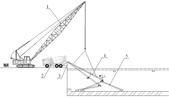
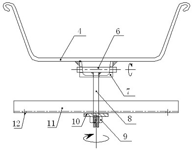
[0016] Such as figure 1 , figure 2 As shown, a deep-founded pit concrete pouring slot includes a enclosure structural steel sheet pile 3, further comprising a first-stage chute 4 and a secondary chute 5; the first step swirl 4 is connected by a snap ring and a serving structural steel sheet pile 3. The first-stage chute 4 can be rotated up and down along the snap ring, and the secondary chute 5 is connected to the first level chute 4, and the secondary chute 5 can rotate 360 ​​° along the horizontal plane of the connection.
[0017] As an embodiment, the rotating shaft assembly includes an upper rotating shaft 6, a upper groove steel 7, a down rotation shaft 8, and a lower groove steel 11;
[0018] The upper groove steel 7 is welded to the bottom of the first stage chute 4, the upper rotating shaft 6 is horizontally mounted in the upper groove steel 7 and can rotate along the axis of the upper rotating shaft 6, and one end of the down rotation shaft 8 is perpendicularly welded to the upper rotating shaft. 6 On the other end, the other end extends through the elliptical hole of the bottom of the upper groove 7 and the lower groove 11, and the lower rotating shaft 8 is attached to the end portion connected to the lower groove steel 11, the spacer 10 and the nut 9 are mounted, and the lower groove steel 11 The two ends are opened with a secondary chute connection hole 12.
[0019] The present invention utilizes steel as a first-stage chute 4, and the light wood structure is used as the secondary chute 5. The two-stage chute is connected by the shaft assembly. Since the secondary chute 5 uses a lightweight wood structure, manual rotation, convenient, high efficiency.
[0020] When used, the first-stage chute 4 is lifted by the track crane 1, and the concrete transport vehicle 2 is transported. The top end of the first-stage chute 4 is connected to the enclosure steel plate pile 3 through the snap ring, so that it is hinged to ensure safety and stability. In case, it is ensured that the primary chute 4 can be rotated up and down; the upper end of the secondary chute 5 is connected to the lower end of the first stage chute 4 to ensure that the secondary chute 5 can be rotated at 360 ° within the horizontal plane. The first-level chute 4 is adjustable, the secondary chute 5 is adjustable, graded, rotated, and greatly increases the coverage of the chute pour.
[0021] The machining parameters of the chute need to be determined according to the width, depth determination of the foundation pit, and the stream trough is determined according to the performance of the collapse, peacetime and other performance. The construction conditions and chute parameters during the S1 section of the Bangaji Dagga Kahopi River Bangladesgi, the S1 Section of the Tunnel, and the chute parameters are as follows:
[0022] Foundation pit 7.7m, the maximum coverage of the chute is 17.5m. The concrete strength grade is C50P10, the collapse is 200 ± 20 mm. The first-level chute length is 10m, U750 × 250 type steel sheet pile (when there is no resources available, the steel is processed), the chute angle is 27 ° ~ 36 °.
[0023] The secondary chute length is 6m, the wood and multilayer plate nails, and the angle is 15 ° ~ 26 °. The efficiency of the pouring concrete is about 40 m3 / h.
[0024] It is only the preferred embodiments of the present invention, and any modifications, equivalents or modifications such as the spirit and equivalents of the present invention should be not intended to limit the invention. Within the range.

PUM

no PUM

Description & Claims & Application Information

We can also present the details of the Description, Claims and Application information to help users get a comprehensive understanding of the technical details of the patent, such as background art, summary of invention, brief description of drawings, description of embodiments, and other original content. On the other hand, users can also determine the specific scope of protection of the technology through the list of claims; as well as understand the changes in the life cycle of the technology with the presentation of the patent timeline. Login to view more.

Similar technology patents

Vertical sliding device for displacement one-way control

ActiveCN111734136AGuarantee the construction qualityGuaranteed smooth progress
Owner:SHANGHAI CONSTRUCTION GROUP +1

Paver parameter setting method based on feed rate

PendingCN107346208AEnsure continuous pavingGuarantee the construction quality
Owner:XCMG CONSTR MACHINERY

Classification and recommendation of technical efficacy words

Why Eureka
Try Eureka