Blasting Vibration Reduction Construction Method of Multiple Pilot Tunnel and Preset Composite Vibration Isolation Layer Close to Tunnel

A construction method and tunnel technology, applied in tunnels, blasting, tunnel lining, etc., can solve the problems of interlayer surrounding rock, limited access surface, and reduced construction efficiency in excessive disturbance, and achieve a reduction in blasting vibration speed and a significant vibration isolation effect. Effect

Active Publication Date: 2022-02-11
QINGDAO TECHNOLOGICAL UNIVERSITY
View PDF11 Cites 0 Cited by
  • Summary
  • Abstract
  • Description
  • Claims
  • Application Information

AI Technical Summary

Problems solved by technology

[0004] (1) The current cutting blasting is basically oblique wedge-shaped cutting blasting. Although the peak value of the maximum vibration velocity has been reduced to a large extent, the maximum peak value of the blasting still occurs during the cutting blasting process. The reason has not been changed. Due to the lack of free face, it is adversely affected by the sandwiching effect of the surrounding rock on the face of the tunnel; (2) Although the traditional mechanical cutting blasting method effectively avoids the vibration peak generated by the cutting blasting, it does not make the leading small pilot hole The effect of creating the free surface is fully exerted, and there is still room for further vibration reduction; (3) The method of mechanical pre-cutting to create the blasting free surface greatly reduces the construction efficiency, and the pre-cutting machine cannot be applied to relatively hard surrounding rock , the cost of mechanical equipment is high and it is not universal; (4) The shock-absorbing blasting of the post-construction tunnel adopts the method of laying a vibration-isolation layer at the bottom of the over-excavated tunnel. (5) The non-blasting method of static crushing requires a pre-grooving machine to cut grooves multiple times and cooperate with static crushers and chemical effect crushing, which has high technical requirements and low construction efficiency
[0005] Although the above current cutting blasting method reduces the blasting vibration velocity to a certain extent, it creates limited free space and sacrifices construction efficiency.

Method used


Image

  • Blasting Vibration Reduction Construction Method of Multiple Pilot Tunnel and Preset Composite Vibration Isolation Layer Close to Tunnel
  • Blasting Vibration Reduction Construction Method of Multiple Pilot Tunnel and Preset Composite Vibration Isolation Layer Close to Tunnel
  • Blasting Vibration Reduction Construction Method of Multiple Pilot Tunnel and Preset Composite Vibration Isolation Layer Close to Tunnel

Examples


Embodiment 1

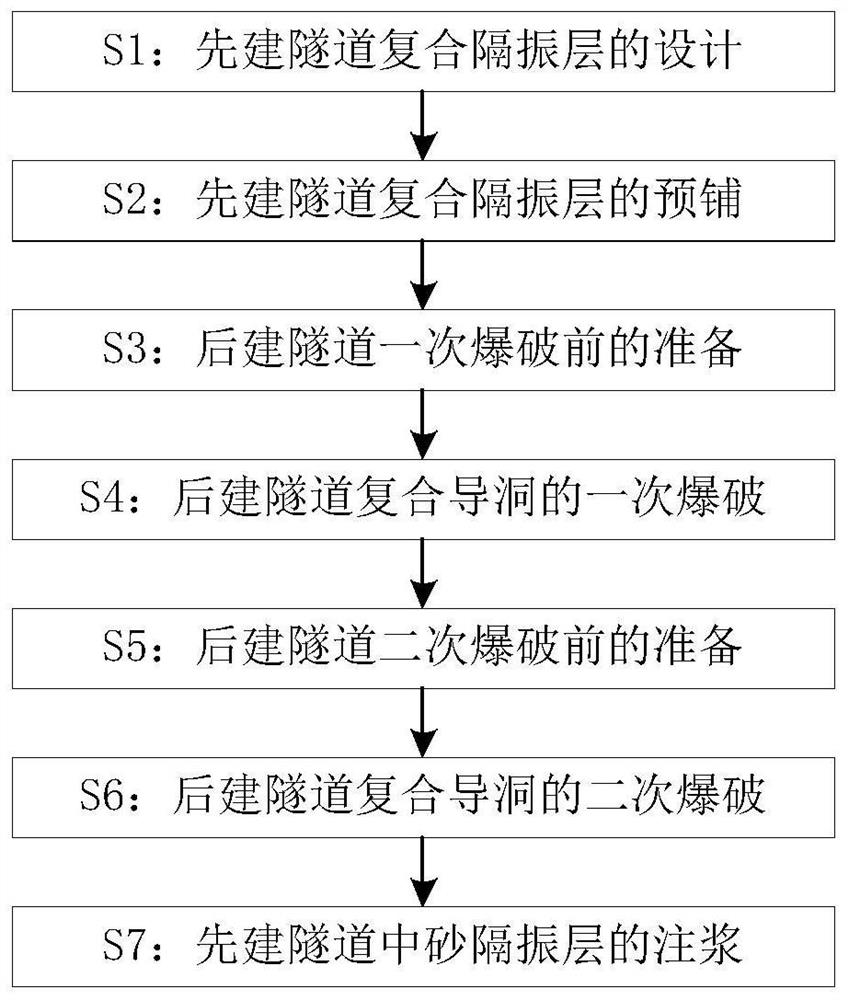
[0065] Such as figure 1 As shown, the multiple pilot tunnel and the preset composite vibration isolation layer of the present invention are close to the blasting vibration reduction construction method of the tunnel, including the following steps:

[0066] S1: Design of the composite vibration isolation layer of the first-built tunnel: According to the construction organization design, before the first-built tunnel 8 passes through the blasting-affected area, it is necessary to judge the intersection angle of the first-built tunnel 8 and the second-built tunnel 9, as follows: Figure 11 As shown, namely:

[0067] When the intersection angle of the tunnel exceeds 60°, the composite vibration isolation layer 10 is respectively laid in the direction of the two tunnels at the closest distance point;

[0068] When the tunnel intersection angle is less than 60°, the laying length of the vibration isolation layer should be extended appropriately depending on the working conditions; ...

Embodiment 2

[0087] In the following, the blasting of the post-constructed tunnel 9 will be described in combination with a specific case.

[0088] Assuming that the surrounding rock 101 around the tunnel is grade III, the first tunnel 8 and the later tunnel 9 will be constructed at the three-dimensional intersection, and the horizontal intersection angle of the two tunnels will be 80°. , the cycle footage is 2m, the blasting material uses plastic nonel, the initiation system is a non-electric millisecond detonator system, the electric detonator is detonated, and the peripheral eye uses small-diameter 40mm rock ammonium nitrate explosives; the selection process of the blasting parameters is as follows:

[0089] Step 1: Take the minimum resistance line of rock as W=1.75m, and calculate the blasting action index:

[0090]

[0091] Step 2: Take the unit explosive consumption as 1.5 after correction according to relevant norms and empirical formulas.

[0092] Step 3: Take 0.90 according to...

Embodiment 3

[0109] The composite vibration isolation layer 10 of the previously built tunnel 8 will be described below in conjunction with a specific case.

[0110] Assuming that the intersection angle between the first tunnel 8 and the later tunnel 9 exceeds 60°, the composite vibration-isolation layer 10 is arranged at a length extending 15m to both sides of the nearest point.

[0111] The type and thickness of each layer of the composite vibration isolation layer 10 are shown in the parameters in the table.

[0112] Table 2 Design parameter list of composite vibration isolation layer 10

[0113]

[0114]The laying position of the composite vibration isolation layer 10 is as attached Figure 12 Shown:

[0115] The beneficial effects of the present invention are: (1) the excavation structure of the face of the multiple pilot tunnel avoids the high peak vibration velocity when the cutting blast creates the free surface, and the creation degree of the free surface is far greater than ...


PUM


Abstract

The invention relates to a blasting and vibration reduction construction method of a multiple pilot tunnel and a preset composite vibration isolation layer close to a tunnel, and belongs to the technical field of controlled blasting of short-distance intersecting tunnels. The present invention comprises the following steps: S1: first build the design of the composite vibration-isolation layer of the tunnel, S2: first build the pre-paving of the tunnel composite vibration-isolation layer, S3: build the tunnel later and prepare for the primary blasting, S4: build the tunnel composite pilot tunnel later S5: Preparation before the secondary blasting of the later-built tunnel, S6: Secondary blasting of the composite pilot tunnel of the later-built tunnel, S7: Grouting of the sand vibration-isolation layer in the first-built tunnel. The invention avoids the high peak vibration velocity generated when the cutting blast creates the air surface through the excavation structure of the face of the multiple guide tunnel, and can effectively reduce the blasting vibration velocity; The tradition of vibration isolation with a single layer of material makes the vibration isolation effect more significant; the combination of multiple pilot tunnels and pre-laid vibration isolation layer measures forms a blasting vibration reduction method that combines active vibration isolation and passive vibration reduction.

Description

technical field [0001] The invention relates to a blasting and vibration reduction construction method of a multiple pilot tunnel and a preset composite vibration isolation layer close to a tunnel, and belongs to the technical field of controlled blasting of short-distance intersecting tunnels. Background technique [0002] The traditional method of blasting excavation by simply using reasonable control of blasting delay uses a non-electric millisecond detonator. Because the delay method is realized by controlling the burning speed of chemical agents, the error is very large due to the influence of the technology level. Under certain circumstances, the detonators of adjacent segments are easy to detonate at the same time, resulting in a large vibration peak. If it adopts an electronic detonator, there are also shortcomings such as the calculation method is not clear, and the price and technical requirements are high. [0003] The current research shows that the maximum blas...

Claims


Application Information

Patent Timeline
Patent Type & Authority Patents(China)
IPC IPC(8): E21D9/00E21D11/00E21D11/10E21D11/38F42D3/04
CPCE21D9/006E21D11/003E21D11/10E21D11/38F42D3/04
Inventor 管晓明杨宁王岗刘泉维刘泽亮汤春阳杨国涛张素磊张鹏杜明庆朱珍牟犇金昕尹鸿威
Owner QINGDAO TECHNOLOGICAL UNIVERSITY
Why Eureka
Try Eureka