
A safe electric fan with cooling function and its manufacturing method

A safe, electric fan technology, applied in manufacturing tools, heating methods, home appliances, etc., can solve problems such as excessive temperature rise, prolonging the cooling time of refrigeration components, and reducing indoor temperature, so as to increase stability and avoid temperature rise Too fast, the effect of prolonging the cooling time

Active Publication Date: 2021-11-26
浙江巴尔电器科技有限公司
View PDF6 Cites 0 Cited by
  • Summary
  • Abstract
  • Description
  • Claims
  • Application Information

AI Technical Summary

Problems solved by technology

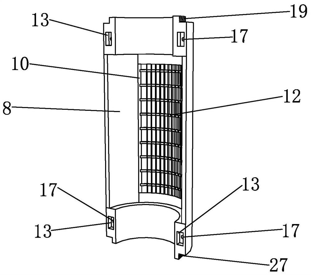
[0004] The purpose of the present invention is to solve the above-mentioned technical problems existing in the prior art, and to provide a safe electric fan with cooling function and a manufacturing method thereof. The bottom of the connecting part is installed in the base, and the top of the shell is provided with a closed assembly, and the cold air is blown out of the shell through the cooling assembly, thereby reducing the indoor temperature. The temperature rises too fast, which effectively prolongs the cooling time of the refrigeration assembly. The setting of the socket part fixes the shell on the base, which increases the stability of the electric fan operation; The rear shell is fixed on the side plate of the installation platform, and the clamping parts are used to fix the rear shell, thereby increasing the stability of the rear shell during assembly and avoiding the shaking of the rear shell during installation phenomenon, which improves the installation accuracy of the shell, and then clamps the front shell by the second clamping part, and the setting of the arc-shaped bracket is used to fit the outer wall of the front shell, thereby increasing the upper clip and the lower clip The integration between the front housing and the connecting rod increases the integration between the upper clamp and the lower clamp, thereby improving the stability of the connection between the front housing and the first clamping member, and then The front shell and the second clamping part are fixed by setting the tightening screw, and the front shell and the rear shell are spliced ​​by driving the sliding frame, the first slider and the second slider respectively, and the Adjust the position of the positioning block on the positioning rod by moving the positioning nut, so as to adjust the length of the positioning rod protruding from the block. The connection between the shell and the rear shell, the setting of the positioning rod not only plays a role in connection, but also plays a role in positioning the installation of the front shell; then fix the socket on the fixed bracket, and clamp it through the clamping block On the outer wall of the socket part, the socket part is fixed on the top of the fixed bracket, and then the first clamping part is driven to move to the side of the fixed bracket. When the housing is above the socket part, it is lifted The parts control the fixed bracket to drive the socket part to rise, and at the same time drive the rotating ring to drive the socket part to rotate, so that the socket part is screwed into the bottom of the shell, avoiding the need for manual installation by multiple workers, and avoiding screwing in If it is not in place, it saves labor and improves installation efficiency and installation accuracy; then fix the assembled cylinder and tower fan in the shell, tighten the connecting sleeve on the top of the shell, and then install the cover Insert it into the limiting groove on the top of the connecting sleeve, and finally remove the shell from the mounting table, and insert it into the base to complete the installation

Method used


Image

  • A safe electric fan with cooling function and its manufacturing method
  • A safe electric fan with cooling function and its manufacturing method
  • A safe electric fan with cooling function and its manufacturing method

Examples


Embodiment Construction

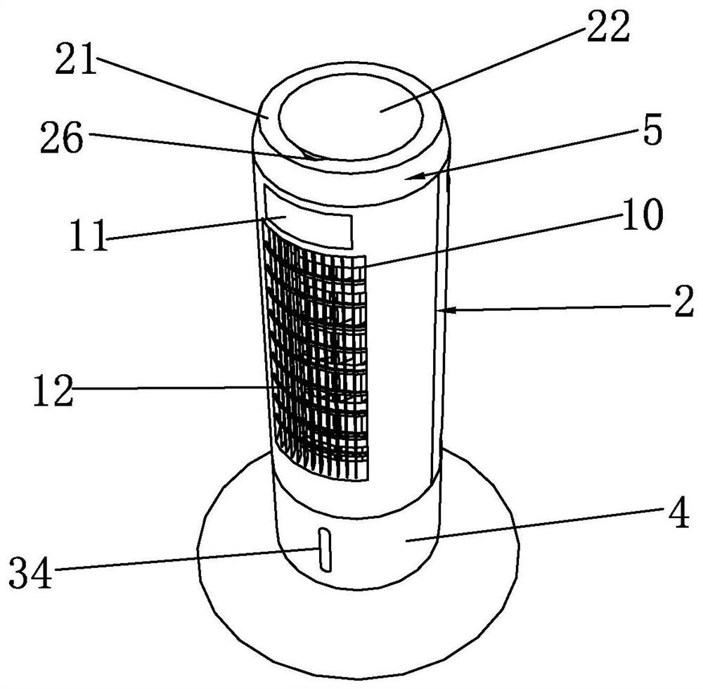
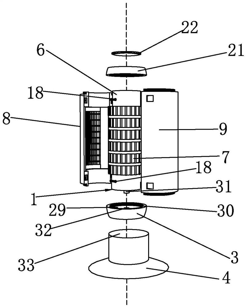
[0045] Such as Figure 1 to Figure 5 As shown, it is a safe electric fan with refrigeration function according to the present invention, which includes a base 4, a refrigeration assembly 1, and a casing 2 sleeved outside the refrigeration assembly 1. The bottom of the casing 2 is provided with a The socket part 3, the socket part 3 is fixedly connected to the bottom of the housing 2, the bottom of the socket part 3 is inserted into the base 4, the top of the housing 2 is provided with a closure assembly 5, and the closure assembly 5 closes the body of the housing 2 top.

[0046] The cooling assembly 1 includes a cylinder 6 and a tower fan 7, the tower fan 7 is rotatably connected to the outside of the cylinder 6, the cylinder 6 is used to store cooling water, and the tower fan 7 blows out the cold air from the cylinder 6. Inject water into the cylinder body 6, and then put ice cubes into the water in the cylinder body 6, the ice cubes will reduce the temperature of the water ...


PUM


Abstract

The invention discloses a safe electric fan with refrigeration function and a manufacturing method thereof, which comprises a base, a refrigeration assembly, and a housing sheathed outside the refrigeration assembly, and the bottom of the housing is provided with a plugging portion matched with the refrigeration assembly , the plugging portion is fixedly connected to the bottom of the housing, the bottom of the plugging portion is inserted into the base, the top of the housing is provided with a closure assembly, and the closure assembly closes the top of the casing; the method includes: a, preparation before installation; b. Assembling the housing; c. Installing the socket; d. Finishing the installation. The invention blows the cold air out of the housing through the refrigeration assembly, thereby reducing the indoor temperature, and the setting of the sealing assembly has a heat preservation effect on the refrigeration assembly, avoiding the temperature of the refrigeration assembly from rising too fast, and effectively prolonging the refrigeration time of the refrigeration assembly. The arrangement of the plug-in part fixes the housing on the base, increasing the stability of the electric fan in operation.

Description

technical field [0001] The invention belongs to the technical field of electric fan equipment, and in particular relates to a safe electric fan with cooling function and a manufacturing method thereof. Background technique [0002] An electric fan is referred to as an electric fan, also known as a fan or a fan. It is a household appliance that uses a motor to drive the fan blades to rotate to accelerate the circulation of air. It is mainly used for cooling, relieving heat and circulating air. Widely used in homes, classrooms, offices, shops, hospitals and hotels and other places. [0003] In the hot summer, when the electric fan is working, due to the current passing through the coil of the electric fan, the wire has resistance, so it will inevitably generate heat and release heat to the outside, which will further increase the indoor temperature and cannot be effectively reduced. temperature, and the use of air conditioners, due to the high power consumption of air conditi...

Claims


Application Information

Patent Timeline
Patent Type & Authority Patents(China)
IPC IPC(8): F24F5/00F24F11/52F24F13/14F24F13/20B25B11/02F04D25/08F04D29/08F04D29/42F04D29/62
CPCB25B11/02F04D25/08F04D29/083F04D29/4226F04D29/626F24F5/0007F24F13/14F24F13/20F24F11/52
Inventor 吕锋平
Owner 浙江巴尔电器科技有限公司
Learn More