Explosion-proof pressure relief transformer

A transformer and pressure relief technology, which is applied in the field of transformers, can solve the problems of reduced strength of the bursting diaphragm, impurities left, uneven material, etc., and achieve the effects of high-speed pressure relief, vacuum pressure bearing, and fire risk avoidance

Active Publication Date: 2021-03-23
BEIJING ZHONGRUIHE ELECTRICAL
View PDF14 Cites 2 Cited by
  • Summary
  • Abstract
  • Description
  • Claims
  • Application Information

AI Technical Summary

Problems solved by technology

The burst pressure is controlled by the weakened structure formed by the slits and holes on the arch surface of the diaphragm. In the burst test and practical application, it is found that when the bursting diaphragm of the positive arch split type is impacted by the internal (concave) pressure, only In the case where some connecting bridge sections are broken and the rest of the connecting bridge sections are not broken, the strength of the bursting diaphragm will be greatly reduced, which will bring hidden dangers to the stable operation of the device, and there may be oil leakage, etc. Phenomenon
The front-arch slotted bursting diaphragm adopts the sealing film as the sealing element. Because the thickness of the sealing film is very thin, micropores may be generated due to uneven material and impurities left in the processing process, which will result in airtightness test and high A small amount of leakage occurs during the vacuum test

Method used


Image

  • Explosion-proof pressure relief transformer
  • Explosion-proof pressure relief transformer
  • Explosion-proof pressure relief transformer

Examples


Embodiment 1

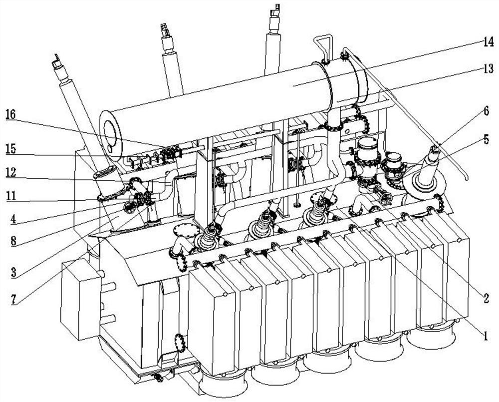
[0044] Such as figure 1 , Figure 5-Figure 18 Shown:

[0045] The invention provides an explosion-proof pressure relief transformer, which includes a transformer main body, on which a main oil tank pressure relief interface 2, a bushing riser seat pressure relief interface 4, and an on-load tap changer pressure relief interface 6 are provided; the main oil tank pressure relief interface 2. The pressure relief port 4 of the casing rising seat and the pressure relief port 6 of the on-load tap changer are respectively equipped with an anti-arch bursting disc pressure relief device; the pressure relief port 2 of the main oil tank, the pressure relief port 4 of the casing rising seat and the The pressure relief port 6 of the on-load pressure regulating switch is respectively connected to the inlet side of the reverse arched bursting disc pressure relief device, and the pressure relief side of the reverse arched bursting disc pressure relief device is connected to the oil discharge...

Embodiment 2

[0056] like figure 1 , figure 2 , image 3 and Figure 4 Shown:

[0057] The difference between this embodiment and Embodiment 1 is that a high-speed pressure relief explosion-proof device (not shown in the figure) is used instead of an anti-arched bursting disc pressure relief device, and the main oil tank 1 or bushing riser 3 of the transformer may have On-load voltage regulating switch 5 carries out explosion-proof protection.

[0058] The invention provides an explosion-proof pressure relief transformer, which includes a transformer main body, on which a main oil tank pressure relief interface 2, a bushing riser seat pressure relief interface 4, and an on-load tap changer pressure relief interface 6 are provided; the main oil tank pressure relief interface 2. A high-speed pressure relief explosion-proof device 17 is respectively installed on the pressure relief port 4 of the bushing rising seat and the pressure relief port 6 of the on-load pressure regulator; the pres...

Embodiment 2

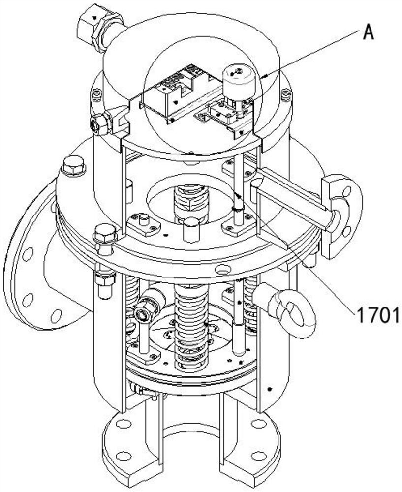
[0062] For Embodiment 2, the difference from Embodiment 1 is that the high-speed pressure relief explosion-proof device 17 is used instead of the reverse arched bursting disc pressure relief device and the decompression chamber 10. When the high-speed pressure relief explosion-proof device 17 starts to release pressure, the indicator rod 1701 Moving upward, during the movement, the indicator rod 1701 will touch the contact of the micro switch 1702 to make it appear in a closed state, and the status signal will be transmitted to other systems through the splitter 1703 in the circuit to realize the action signal alarm function . Other contents are the same as those in Embodiment 1, and will not be repeated here.


PUM


Abstract

The invention provides an explosion-proof pressure relief transformer which comprises a transformer main body, wherein the transformer main body is provided with a main oil tank pressure relief connector, a sleeve ascending flanged base pressure relief connector and an on-load tap changer pressure relief connector, wherein the pressure relief connectors are respectively provided with a high-speedpressure relief explosion-proof device or an inverted-arch rupture disk pressure relief device; the inverted-arch rupture disk pressure relief device comprises an inverted-arch rupture disk, an inletside clamp holder and a pressure relief side clamp holder, and the inverted-arch rupture disk is clamped and fixed by the inlet side clamp holder and the pressure relief side clamp holder. Compared with a positive-arch-shaped slotted diaphragm, the inverted-arch-shaped blasting diaphragm does not have a diaphragm slot, the trace leakage phenomenon is prevented, and the sealing performance is greatly improved; the bursting pressure value of the inverted-arch-shaped diaphragm can be closer to the working pressure value, so that the long-term reliability is better; and moreover, the installationposition is close to a fault-prone point as much as possible, a conical pipe joint is adopted, compared with a straight pipe type pressure relief channel, the flow resistance loss is reduced, and oneor more pressure relief devices are installed on a piece to be subjected to pressure relief, so that effective protection is achieved.

Description

technical field [0001] The invention relates to the technical field of transformers, in particular to an explosion-proof voltage relief transformer. Background technique [0002] Oil-immersed transformers contain a large amount of transformer oil, which is prone to explosion hazards in the event of high-energy faults. Therefore, the transformer must be protected against explosion. At present, the main solution to prevent transformer explosion in the world is to install pressure relief valves or positive arched metal burst diaphragms on the transformer body, on-load tap changer and other parts as pressure relief devices for protection. In recent years, many phenomena such as transformer explosions and fires have occurred from the bushing riser. However, in all current technologies, there is no explosion-proof pressure relief protection for the riser. [0003] The latest explosion-proof technology adopts the positive arch bursting diaphragm as the main explosion-proof compon...

Claims


Application Information

Patent Timeline
Patent Type & Authority Applications(China)
IPC IPC(8): H01F27/14H01F27/40F16K17/16
CPCH01F27/14H01F27/40F16K17/1606
Inventor 朱述友周贤武路文文闫永固
Owner BEIJING ZHONGRUIHE ELECTRICAL
Why Eureka
Try Eureka