
Non-reciprocal circuit element

一种电路元件、端子电极的技术,应用在不可逆电路元件领域,能够解决成形复杂等问题,达到简化形状、抑制制造成本的效果

Active Publication Date: 2021-03-23
TDK CORPARATION
View PDF16 Cites 0 Cited by
  • Summary
  • Abstract
  • Description
  • Claims
  • Application Information

AI Technical Summary

Problems solved by technology

However, the conventional nonreciprocal circuit element disclosed in Patent Document 1 has a complicated structure by insert molding a resin case including external terminals.

Method used


Image

  • Non-reciprocal circuit element
  • Non-reciprocal circuit element
  • Non-reciprocal circuit element

Examples


Embodiment Construction

[0069] Hereinafter, preferred embodiments of the present invention will be described in detail with reference to the accompanying drawings.

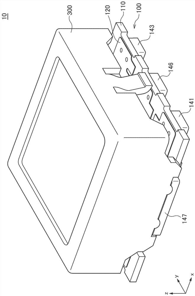
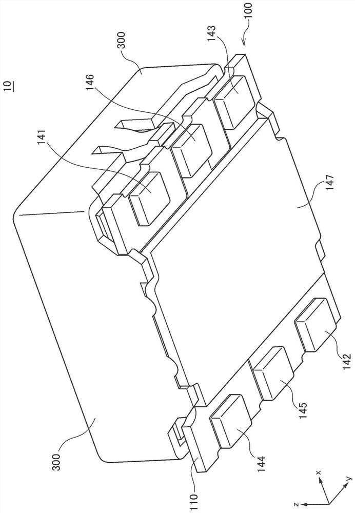
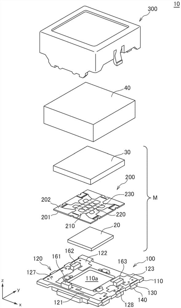
[0070] figure 1 and figure 2 is a schematic perspective view showing the appearance of a nonreciprocal circuit element 10 according to a preferred embodiment of the present invention, figure 1 It is a figure seen from the upper side, figure 2 It is a figure seen from the bottom. in addition, image 3 It is a schematic exploded perspective view for explaining the structure of the nonreciprocal circuit element 10 according to this embodiment.

[0071] The nonreciprocal circuit element 10 according to the present embodiment is a surface mount type nonreciprocal circuit element such as Figure 1 ~ Figure 3 As shown, it includes a circuit board unit 100 , a laminated structure 200 , ferrite cores 20 and 30 , a permanent magnet 40 , and a case-shaped upper yoke 300 . Such as image 3 As shown, the laminated structure 200 has a structu...


PUM


Abstract

In a surface-mounted nonreciprocal circuit element having the structure in which a magnetic rotor is mounted on a substrate, the shape of the substrate is simplified, thereby suppressing manufacturingcost. The reversible circuit element (10) includes: a substrate (110); a magnetic metal layer (140) provided on the lower surface of the substrate (110); a magnetic rotor (M) provided on the upper surface of the substrate (110); a magnetic rotor (M) provided on the upper surface of the substrate (110); and a permanent magnet (40) that applies a magnetic field to the magnetic rotor (M).The magnetic metal layer (140) includes a lower yoke (147) provided at a position overlapping the magnetic rotor (M) in a plan view; and a plurality of terminal electrodes (141- 146) connected to the magnetic rotor (M).In this way, as the magnetic metal layer (140) provided on the lower surface of the substrate (110) functions as a lower yoke (147) and the terminal electrodes (141 to 146), there is no need to wind the lower yoke from the side surface of the substrate to the lower surface. The invention eliminates the need for processing such as partially reducing thickness of the substrate, so that the manufacturing cost can be suppressed.

Description

technical field [0001] The present invention relates to a nonreciprocal circuit element, and more particularly to a surface mount type nonreciprocal circuit element having a structure in which a magnetic rotor is mounted on a substrate. Background technique [0002] A nonreciprocal circuit element such as an isolator or a circulator, which is a type of magnetic device, has a structure in which necessary components such as a magnet rotor are housed in a magnetic metal container that functions as a yoke. This magnetic metal container also functions as a grounding member, and can be used as an external terminal for grounding. On the other hand, signal input / output terminals need to be formed separately, and a structure for leading out electric signals to the outside of the metal container is needed. That is, the signal input / output terminals need to pass through the magnetic metal container constituting the bottom of the product and be drawn out to the outside. [0003] As a ...

Claims


Application Information

Patent Timeline
Patent Type & Authority Applications(China)
IPC IPC(8): H01P1/32
CPCH01P1/32H01P1/375H01P1/393H01P1/387H01F7/02H01P1/383
Inventor 渡边悦绍
Owner TDK CORPARATION
Learn More