Decoupling control method and device for continuous working mode power factor correction converter

A technology of power factor correction and working mode, applied in the direction of output power conversion device, climate sustainability, high-efficiency power electronic conversion, etc., can solve the problems of input current distortion and affecting the transient response capability of converter load, etc.

Inactive Publication Date: 2021-03-23
SOUTHWEST JIAOTONG UNIV
View PDF3 Cites 5 Cited by
  • Summary
  • Abstract
  • Description
  • Claims
  • Application Information

AI Technical Summary

Problems solved by technology

When the bandwidth of the voltage control loop is large, although a faster transient response can be achieved, the double power frequency ripple in the output voltage will be introduced into the current reference signal I ref , which distorts the input current
In order to obtain a high power factor, the bandwidth of the voltage control loop is usually designed to be small, but the small bandwidth will affect the load transient response capability of the converter

Method used


Image

  • Decoupling control method and device for continuous working mode power factor correction converter
  • Decoupling control method and device for continuous working mode power factor correction converter
  • Decoupling control method and device for continuous working mode power factor correction converter

Examples


Embodiment Construction

[0056] In order to make the object, technical solution and advantages of the present invention clearer, the present invention will be described in detail below in conjunction with the accompanying drawings. Apparently, the described embodiments are only some of the embodiments of the present invention, but not all of them. Based on the embodiments of the present invention, all other embodiments obtained by persons of ordinary skill in the art without making creative efforts belong to the protection scope of the present invention.

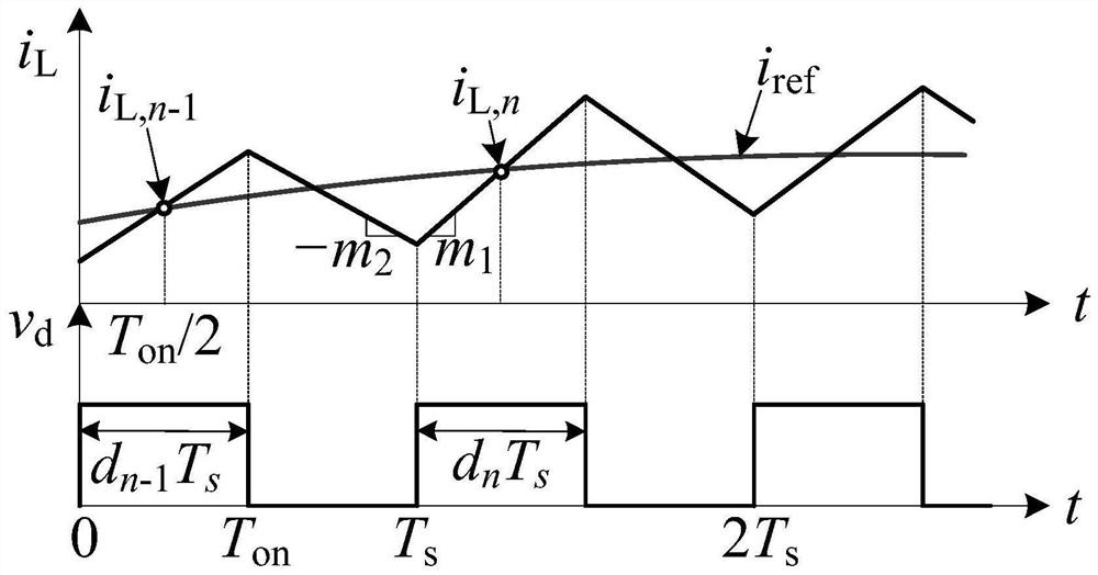
[0057] Such as figure 1 As shown, for the continuous operation mode power factor correction converter (hereinafter referred to as CCM PFC), the average value of the inductor current i L,ave equal to the inductor current during each switching cycle T on The instantaneous value at time / 2, i.e. i L,n-1 = i L,n = i L,ave , where T on is the on-time, i L,n-1 and i L,n are the sampling values ​​of the inductor current in the n-1th switching cycle...


PUM


Abstract

The invention discloses a decoupling control method and device for a continuous working mode power factor correction converter. The method comprises the steps of: firstly detecting the keyparameters such as output voltage, the rectified input voltage, the inductive current and the load current of the continuous working mode power factor correction converter at the beginning of each switching period; respectively calculating the duty ratio of a current control loop and the duty ratio of a voltage control loop in each switching period according to the detected key parameters, and adding the dutyratios to obtain a duty ratio signal of the power factor correction converter in the continuous working mode in each switching period; and finally, controlling the on-off of a switching tube in the continuous working mode power factor correction converter according to the calculated duty ratio signal. According to the decoupling control method and device of the invention, the voltage control loopand the current control loop can be decoupled from each other, so that double power frequency ripples of output voltage cannot be introduced into the current control loop, a high power factor and lowinput current distortion are ensured, and meanwhile, the transient response speed and reliability of the power factor correction converter are improved.

Description

technical field [0001] The invention relates to a power factor correction converter (Power Factor Correction, PFC), in particular to a decoupling control method for a power factor correction converter in a continuous operation mode, and a device for realizing the decoupling control method. Background technique [0002] The power factor correction converter can reduce the harmonic pollution of power electronic devices to the public grid, and has the advantages of high power factor, small size, and low cost. The power factor correction converter working in the inductor current continuous mode (CCM) usually adopts the average current (ACM) control method, because of its advantages of high input power factor, small current ripple, strong anti-interference ability, and constant switching frequency, it is very Suitable for medium and high power occasions. [0003] The traditional average current control has two control loops, the voltage control loop is used to control the output...

Claims


Application Information

Patent Timeline
Patent Type & Authority Applications(China)
IPC IPC(8): H02M1/42
CPCH02M1/4225Y02B70/10
Inventor 沙金郭帅军许建平胡嘉豪
Owner SOUTHWEST JIAOTONG UNIV
Why Eureka
Try Eureka