
Compact endoscope surgical robot end driving structure

A surgical robot and driving structure technology, applied in the field of medical devices, can solve the problems of the auxiliary operation speed and auxiliary operation effect affecting the doctor, the limitation of the operation space of the mechanical arm, and the multi-space, etc., so as to reduce mutual interference, reduce the structure space, The effect of reducing the footprint

Pending Publication Date: 2021-03-26
SHANGHAI SIMPLE TOUCH TECH CO LTD
View PDF0 Cites 1 Cited by
  • Summary
  • Abstract
  • Description
  • Claims
  • Application Information

AI Technical Summary

Problems solved by technology

[0002] At present, the end drive structure of the existing endoscopic minimally invasive robot system is a linear drive structure. This structure is generally composed of actuators that are longer than the motion stroke, such as guide rails and corresponding screw rods or belts. Therefore, its own The length is generally greater than the movement stroke of the end. This structure needs to occupy more space, and in the process of multi-arm cooperation, it often occurs that the drive structures at the end interfere with each other, so the operating space of the robot arm will be reduced. Restricted, it is not conducive to realizing the requirements of various motion postures in the complex operation process, and often affects the normal operation speed and auxiliary operation effect of the doctor's auxiliary operation

Method used


Image

  • Compact endoscope surgical robot end driving structure
  • Compact endoscope surgical robot end driving structure
  • Compact endoscope surgical robot end driving structure

Examples


Embodiment Construction

[0018] Below in conjunction with accompanying drawing, the present invention will be further described as follows:

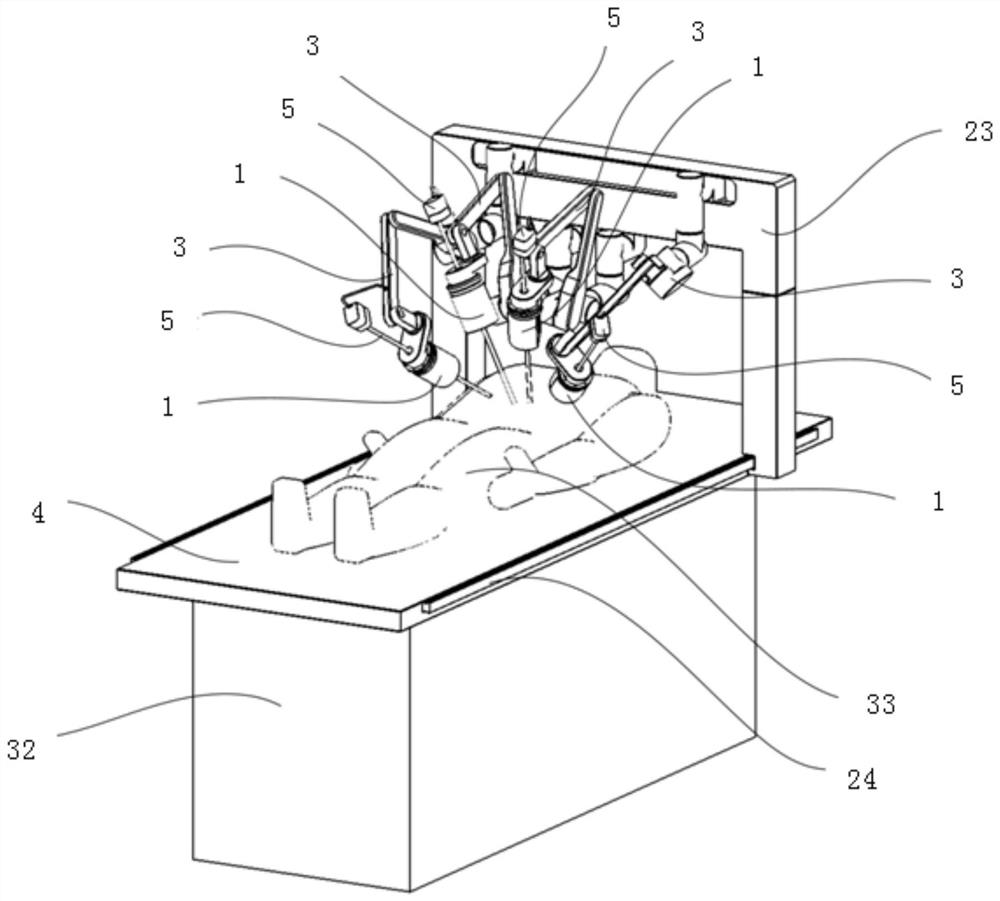
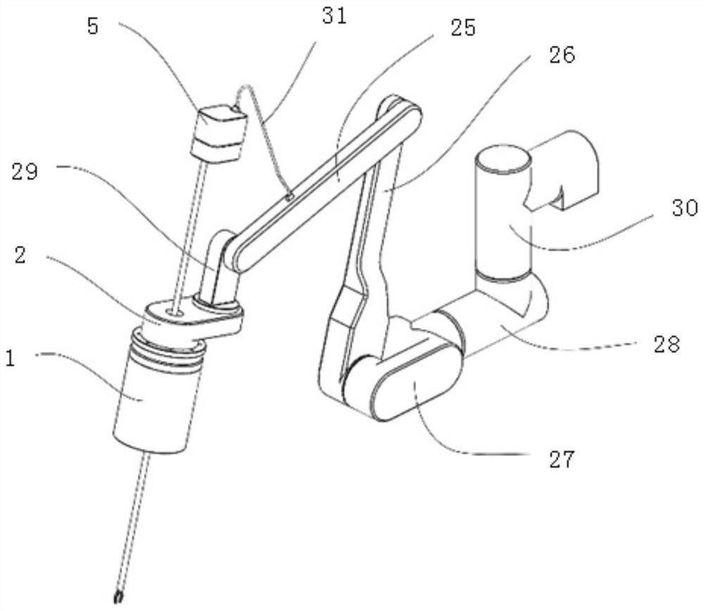
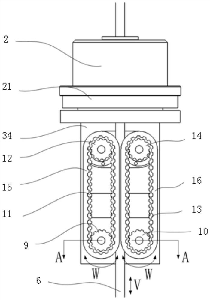
[0019] The present invention provides a compact endoscopic surgical robot terminal drive structure, including a surgical terminal drive mechanism 1, the surgical terminal drive mechanism 1 is installed on the drive mechanism base 2, the drive mechanism base 2 is installed at the end of the mechanical arm 3, the mechanical arm 3 is set above the bed board 4, the operating end driving mechanism 1 is connected to the surgical instrument 5, and the slender rod 6 of the surgical instrument 5 passes through the middle channel of the operating end driving mechanism 1, and the operating end driving mechanism 1 includes a linear motion mechanism and a rotary motion mechanism, The slender rod 6 of the surgical instrument 5 performs linear motion and rotary motion driven by the linear motion mechanism and the rotary motion mechanism.

[0020] as attached image 3 And atta...


PUM


Abstract

The invention relates to a compact endoscope surgical robot end driving structure. The compact endoscope surgical robot end driving structure comprises surgical end driving mechanisms; the surgical end driving mechanisms are installed on driving mechanism bases; the driving mechanism bases are installed at the tail ends of mechanical arms; the mechanical arms are arranged above a bed board; the surgical end driving mechanisms are connected with surgical instruments; slender rods of the surgical instruments pass through middle channels of the surgical end driving mechanisms; each surgical end driving mechanism comprises a linear motion mechanism and a rotary motion mechanism; the slender rods of the surgical instruments are driven by the linear motion mechanisms and the rotary motion mechanisms to do linear motion and rotary motion; the mechanical arms are connected to a movable frame; the movable frame is arranged above the bed board in a striding mode; translation guide rails are installed on the left and right sides of the bed board; and the movable frame moves horizontally along the translation guide rails. According to the invention, the structural space of the surgical ends ofthe mechanical arms can be greatly reduced, the possibility of mutual interference of the tail ends of the mechanical arms is reduced, and more possible operation space is provided for clinicians.

Description

[technical field] [0001] The invention relates to the technical field of medical instruments, in particular to a compact endoscopic surgical robot terminal driving structure. [Background technique] [0002] At present, the end drive structure of the existing endoscopic minimally invasive robot system is a linear drive structure. This structure is generally composed of actuators that are longer than the motion stroke, such as guide rails and corresponding screw rods or belts. Therefore, its own The length is generally greater than the movement stroke of the end. This structure needs to occupy more space, and in the process of multi-arm cooperation, it often occurs that the drive structures at the end interfere with each other, so the operating space of the robot arm will be reduced. It is restricted, which is not conducive to realizing the requirements of various motion postures in the complex operation process, and often affects the normal operation speed and auxiliary opera...

Claims


Application Information

Patent Timeline
Patent Type & Authority Applications(China)
IPC IPC(8): A61B34/30
CPCA61B34/30A61B2034/302
Inventor 路迎
Owner SHANGHAI SIMPLE TOUCH TECH CO LTD
Learn More