

Reference circle positioning clamp for cylindrical inner gear rings
A technology for positioning fixtures and internal gears, which is applied in the direction of gear teeth, gear cutting machines, manufacturing tools, etc., can solve the problems of inconvenient mass production and complicated fixture operation, and achieve convenient mass production, good self-positioning effect, and direct and effective positioning Effect
- Summary
- Abstract
- Description
- Claims
- Application Information
AI Technical Summary
Problems solved by technology
Method used
Image

Examples
Embodiment 1
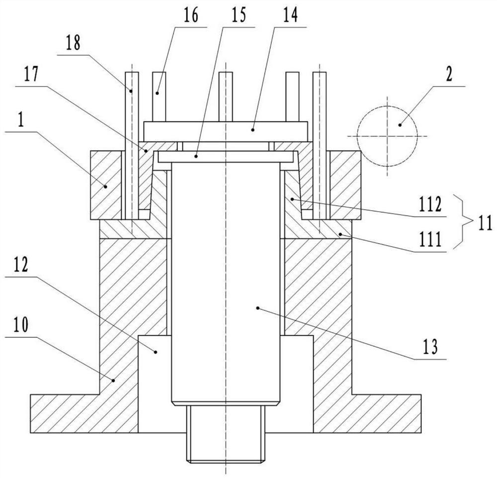
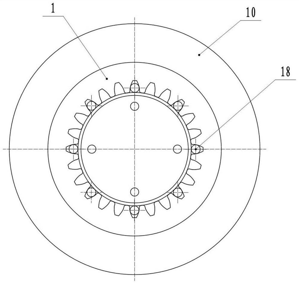
[0027] Basic as attached figure 1 and figure 2 Shown: Cylindrical internal ring gear 1 indexing circle positioning fixture, including a base 10 fixedly arranged on the processing machine tool, a positioning seat 11 is provided on the base 10, and a positioning position that communicates with each other is provided in the middle of the positioning seat 11 and the base 10 Holes 12, wherein the positioning hole 12 is a circular hole, and a pull rod 13 is arranged in the circular hole, wherein the pull rod 13 and the positioning hole 12 are splined, that is, the pull rod 13 can move up and down along the positioning hole 12, and Cannot be rotated.
[0028] The top of the pull rod 13 is provided with a supporting round platform 15, and the supporting round platform 15 is detachably connected with a clamping platform 14. Specifically, the bottom of the clamping platform 14 is provided with a screw rod, and the top of the supporting circular platform 15 is provided with a threaded ...
Embodiment 2
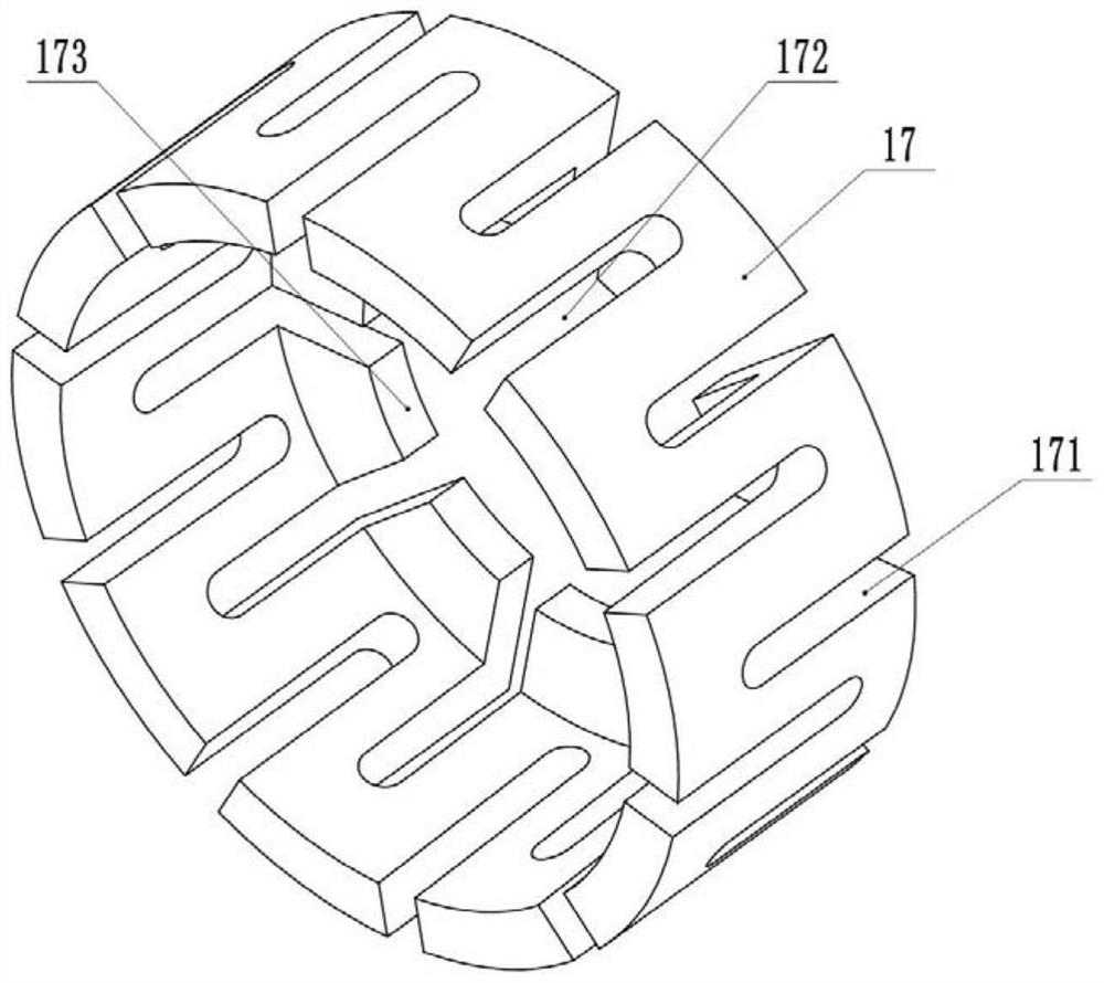
[0034] The difference from Example 1 is: the combination image 3 As shown, the expansion grooves arranged in the circumferential direction of the expansion sleeve 17 include a top groove 171 and a bottom groove 172, wherein the top groove 171 and the bottom groove 172 are arranged at intervals, that is, the two sides of the top groove 171 are the bottom groove 172, and the two sides of the bottom groove 172 The side is the top groove 171, the bottom groove 172 means that the bottom of the expansion groove is connected with the bottom of the expansion sleeve 17, and the top is not connected with the through hole 173; while the top groove 171 means that the top of the expansion groove is connected with the through hole 173, and the top of the expansion groove is connected with the through hole 173. The bottom is not connected with the bottom of the expansion sleeve 17. Such setting can make the expansion sleeve 17 fit well with the cylinder 112, so as to expand outward.
Embodiment 3
[0036] The difference from Embodiment 2 is that a positioning groove penetrating up and down is provided between the adjacent bottom groove 172 and the top groove 171, wherein the cross section of the positioning groove is arc-shaped, and the radius of the arc is greater than the radius of the steel bar. In this way, the steel rod can be snapped into the positioning groove, and a layer of rubber layer is bonded on the inner wall of the positioning groove, which can improve the friction between the positioning groove and the steel rod, and prevent the steel rod from moving downward in the expansion sleeve 17 on the one hand. On the other hand, the radial runout between the steel rod and the inner ring gear 1 and the expansion sleeve 17 is further prevented during the gear hobbing process.
PUM
 Abstract
Description
Claims
Application Information