
Refrigerator drawer injection mold

An injection mold and drawer technology, which is applied in the field of refrigerator drawer injection molds, can solve the problems affecting product production quality, inconvenient and rapid material retrieval, and inability to quickly fill, and achieves the effects of novel design, high degree of automation, and guaranteed production quality.

Pending Publication Date: 2021-03-26
CHUZHOU DIMENGDE MOLD MFG
View PDF4 Cites 9 Cited by
  • Summary
  • Abstract
  • Description
  • Claims
  • Application Information

AI Technical Summary

Problems solved by technology

[0004] The invention proposes a refrigerator drawer injection mold, which solves the problem that the existing injection mold cannot be quickly filled after injection molding, and there are easy gaps, which affect the production quality of the product, and are inconvenient to quickly take materials.

Method used


Image

  • Refrigerator drawer injection mold
  • Refrigerator drawer injection mold
  • Refrigerator drawer injection mold

Examples


Embodiment 1

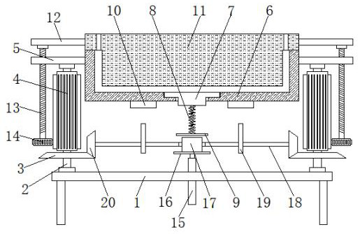
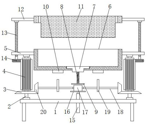
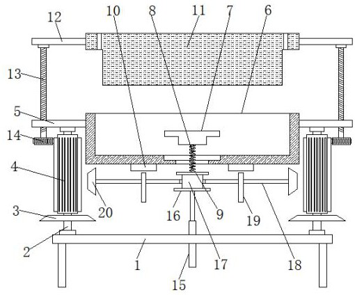
[0028] refer to Figure 1-3 , Image 6 An injection mold for a refrigerator drawer, comprising a placing plate 1, a transmission mechanism is arranged on both sides of the top of the placing plate 1, a fixed plate 5 is connected to the top of the transmission mechanism in rotation, and a lower mold 6 is fixedly connected between the two fixed plates 5, The movable cover at the bottom of the lower die 6 is provided with an ejection mechanism, the top of the lower die 6 is provided with a patrix 11, the two sides of the patrix 11 are provided with a lifting mechanism, and the inner fixed sleeve of the placing plate 1 is provided with a push rod motor 15, which pushes The output shaft of the rod motor 15 is fixedly connected with a driving vibration mechanism, and the bottom of the lower mold 6 is fixedly connected with two elastic blocks 10 .

[0029] In the present invention, the transmission mechanism includes a rotating shaft 2 that is rotatably connected to the top of the p...

Embodiment 2

[0036] refer to Figure 3-5 : An injection mold for a refrigerator drawer. In this embodiment, after the injection molding and vibration operations are completed, the push rod motor 15 drives the driving vibration mechanism to move down again, so that the first bevel gear 3 and the second bevel gear 20 are meshed again to drive the vibration The mechanism drives the lifting mechanism to work through the transmission mechanism. The lifting mechanism will drive the upper mold 11 to move upward. At this time, the push rod motor 15 will drive the driving vibration mechanism to move upward again. The driving vibration mechanism will squeeze the ejection mechanism. The ejection mechanism includes movable sleeves. In the lifting plate 7 inside the lower die 6, the bottom of the lifting plate 7 is fixedly connected with a spring 8, and the bottom end of the spring 8 is fixedly connected with a movable plate 9, so that the movable plate 9 and the spring 8 will move upwards under the pre...


PUM


Abstract

The invention discloses a refrigerator drawer injection mold, and relates to the technical field of refrigerator drawer production. According to the following scheme aiming at the problems that an existing injection mold cannot be quickly filled after injection molding, gaps easily exist, the production quality of products is influenced, and materials are inconvenient to take quickly: the refrigerator drawer injection mold comprises a placing plate, transmission mechanisms are arranged on the two sides of the top of the placing plate, the tops of the transmission mechanisms are rotationally connected with fixing plates, a lower mold is fixedly connected between the two fixing plates, the bottom of the lower mold is movably sleeved with an ejection mechanism, the top of the lower mold is provided with an upper mold, the two sides of the upper mold are provided with lifting mechanisms, and the a push rod motor is fixedly sleeved with the interior of the placing plate. Closing and openingof the upper mold and the lower mold are conveniently and automatically controlled, vibration during injection molding is convenient, sufficient injection molding is facilitated, the production quality of products is guaranteed, meanwhile, after injection molding, the products are conveniently and rapidly taken out, operation is simple and fast, and the automation degree is high.

Description

technical field [0001] The invention relates to the technical field of refrigerator drawer production, in particular to an injection mold for a refrigerator drawer. Background technique [0002] Injection molding, also known as injection molding, is a molding method of injection and molding. The advantages of the injection molding method are fast production speed, high efficiency, automatic operation, various designs and colors, simple to complex shapes, large to small sizes, accurate product sizes, easy replacement of products, and complex shapes. Parts, injection molding is suitable for mass production and complex shape products and other molding processing fields. At a certain temperature, the completely molten plastic material is stirred by a screw, injected into the mold cavity with high pressure, and cooled and solidified to obtain a molded product. This method is suitable for mass production of parts with complex shapes and is one of the important processing methods...

Claims


Application Information

Patent Timeline
Patent Type & Authority Applications(China)
IPC IPC(8): B29C45/26B29C45/40B29C45/17
CPCB29C45/26B29C45/4005B29C45/17
Inventor 朱余宏冯顺
Owner CHUZHOU DIMENGDE MOLD MFG
Learn More