A reverse-wrapped capsule vulcanization device and vulcanization method

A bladder and vulcanization mold technology, which is applied in the field of tire molding, can solve the problems of reducing the service life of the turn-up bladder, affecting the vulcanization effect by air gaps, and prone to tearing at folding points, so as to improve the vulcanization heating effect, good vulcanization effect, and high-quality products. The effect of long service life

Active Publication Date: 2021-05-14
YONGYI RUBBER CO LTD
View PDF18 Cites 0 Cited by
  • Summary
  • Abstract
  • Description
  • Claims
  • Application Information

AI Technical Summary

Problems solved by technology

However, this vulcanization method has the following problems: first, when the reverse-encapsulated capsule obtained by this vulcanization method is vulcanized, the folding points of the A surface and the B surface, and the folding points of the B surface and the C surface are prone to adhesion during the vulcanization process , when the reverse-wrapped capsule is inflated, the folded point where adhesion occurs is prone to tearing, reducing the service life of the reverse-wrapped capsule
Second, because the thickness of the folded vulcanization bladder is large, and there is an air gap in the folded part, which affects the vulcanization effect
[0005] The second of the existing reverse-wrapped capsule production process is to adopt a straight cylinder structure vulcanization device for vulcanization, and the vulcanized reverse-wrapped capsule ( Figure 15 )’s A and C faces are folded inward to form the final product, but this process has the following disadvantages. First, water-wrapped cloth is used to fix the vulcanization process. The vulcanization quality depends on the technical quality of the workers. Winding density, angle and strength will have a certain impact on the product
Second, during the turning process of the vulcanized turn-up capsule, due to its small inner radius and large outer radius, the rubber product is prone to fatigue, which will easily lead to cracks in the long run and affect the life of the tire

Method used


Image

  • A reverse-wrapped capsule vulcanization device and vulcanization method
  • A reverse-wrapped capsule vulcanization device and vulcanization method
  • A reverse-wrapped capsule vulcanization device and vulcanization method

Examples


specific Embodiment approach

[0063] It should be noted that the structures, proportions, sizes, etc. shown in the drawings attached to this specification are only used to match the content disclosed in the specification, for those who are familiar with this technology to understand and read, and are not used to limit the implementation of the present invention Any modification of structure, change of proportional relationship or adjustment of size shall fall within the range covered by the technical content disclosed in the present invention without affecting the effect and purpose of the present invention. within range.

[0064] At the same time, terms such as "upper", "lower", "left", "right", "middle" and "one" quoted in this specification are only for the convenience of description and are not used to limit this specification. The practicable scope of the invention and the change or adjustment of its relative relationship shall also be regarded as the practicable scope of the present invention without...

Embodiment 1

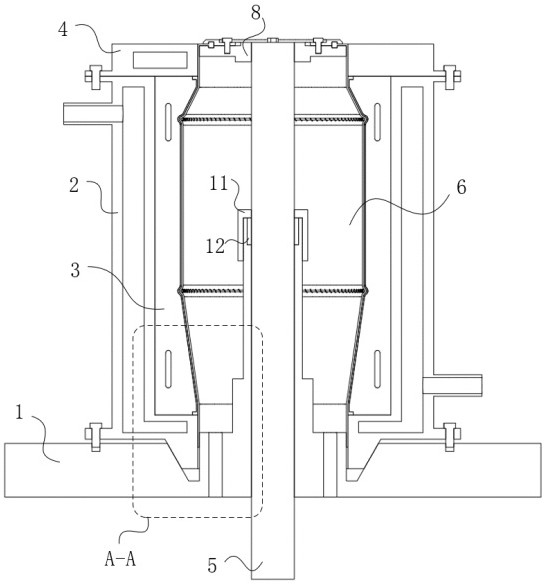
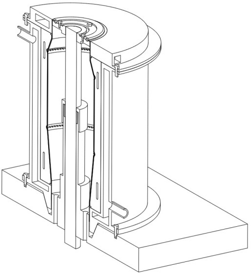
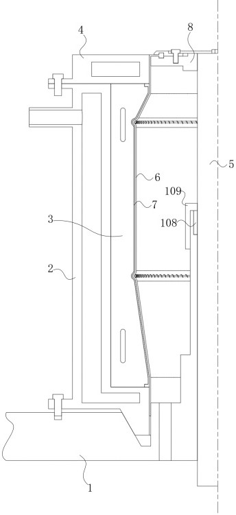
[0066] This embodiment provides a reverse-encapsulation bladder vulcanization device, comprising a base 1, a heating jacket 2, a vulcanization mold 3, an upper platen 4 and a vulcanization bladder 6, the upper platen 4 is fixed on the top of the heating jacket 2, the bottom of the heating jacket 2 is connected to the base 1 is fixed, the vulcanization mold 3 is installed in the heating jacket 2, which has the outer surface of the turned-up capsule and the outer surface of the spigot, the vulcanization bladder 6 is installed in the vulcanization mold 3, and has the inner surface of the turned-up capsule and the inner side of the slit On the surface, the heating jacket 2 has a cylindrical structure, and a first flange 24 and a second flange 25 are respectively arranged below and above the cylinder body 21. The cylinder body 21 has a first flow path 201 inside, and the first flow path 201 is L-shaped. The annular flow path communicates with the first inlet 22 and the first outlet ...

Embodiment 2

[0076] The first bladder bend 67 and the second bladder bend 68 in the vulcanization bladder 6 are provided with a support spring 69a, and the support spring 69a is vulcanized and solidified together with the first bladder bend 67 and the bladder second bend 68 .

[0077] A kind of optimized vulcanization bladder 6 is provided in the present embodiment, and support spring 69a is set at two bends of vulcanization bladder 6, and this support spring 69a can provide good resistance to the bend of turn-up capsule in the vulcanization process. The supporting function makes the bending part of the turn-up capsule less likely to be deformed during the vulcanization process. Simultaneously, when the reverse-wrapped capsule is taken and placed, the vulcanizing bladder 6 needs to be stretched, so that the middle part of the capsule body shrinks, which is convenient for taking and placing the reverse-wrapped capsule. Contraction occurs in the middle.


PUM


Abstract

The invention relates to the technical field of tire building, in particular to a reverse capsule vulcanization device and a vulcanization method. A reverse capsule vulcanization device, including a base, a heating mantle, a vulcanization mold, an upper platen and a vulcanization bladder, the upper platen is fixed on the top of the heating mantle, and the bottom of the heating mantle is fixed to the base, through the external vulcanization mold and the internal vulcanization bladder The reverse-wrapped capsule is vulcanized, the vulcanization degree is uniform, and the vulcanization effect is good. By setting the bending corresponding to the folded position of the turned-up capsule on the vulcanization mold and the vulcanized capsule, the vulcanization quality of the turned-up capsule at the bend is guaranteed. The treatment of the capsule at the bend can avoid the rubber fatigue caused by the folding of the vulcanized capsule, and the reverse-packed capsule produced by the device and the method has a high qualified rate and a long service life of the product.

Description

technical field [0001] The invention relates to the technical field of tire building, in particular to a reverse capsule vulcanization device and a vulcanization method. Background technique [0002] The turn-up capsule is a commonly used device on the tire building machine. It is used to realize the lamination of the inner liner and the cord, and the turn-up operation after the buckle, so that there is no gap between the bead wire and the cord layer. Delamination, no bubble phenomenon. [0003] The raw materials of reverse-wrapped capsules are mainly made of natural rubber, butadiene rubber, carbon black and other auxiliary ingredients, and the made reverse-wrapped capsule embryos need to be vulcanized under certain conditions of time, temperature and pressure to obtain finished capsules . [0004] One of the existing turn-up capsule production techniques is to place the molded vulcanization capsule directly on a special vulcanizer for vulcanization. Such as Figure 21 A...

Claims


Application Information

Patent Timeline
Patent Type & Authority Patents(China)
IPC IPC(8): B29D30/06B29C35/04B29C35/00B29L30/00
CPCB29C35/002B29C35/007B29C35/049B29D30/0601B29L2030/00
Inventor 赵海林韩正奇赵会岩刘海军张学永刘涛
Owner YONGYI RUBBER CO LTD
Why Eureka
Try Eureka