Cleaning device for textile machinery and using method of cleaning device

A technology for textile machinery and cleaning devices, which is applied in textiles, textiles, papermaking, knitting, etc., can solve the problems of large cleaning devices, rusty textile machinery, and low flexibility, and achieve a large cleaning range, prolong service life, and improve The effect of flexibility

Inactive Publication Date: 2021-03-26
诸暨市惠联精密机械制造有限公司
View PDF6 Cites 2 Cited by
  • Summary
  • Abstract
  • Description
  • Claims
  • Application Information

AI Technical Summary

Problems solved by technology

[0004] The purpose of the present invention is to provide a cleaning device for textile machinery. By installing a blower instead of water and brushes, it solves the problem that textile machinery often leaves some cloth debris after weaving the cloth. If it is not cleaned in time, it may be damaged. Cloth residues cause blockage to the machine. Traditional textile machinery cleaning devices use water and brushes to clean them. However, after soaking in water, the fabric residues tend to form into balls, which is more It is difficult to clean, and the water will make the textile machinery rust. By setting the universal wheel, the movement of the equipment is convenient, and the cleaning device of the traditional textile machinery is generally large in size, heavy in weight, and low in flexibility. difficulty moving

Method used


Image

  • Cleaning device for textile machinery and using method of cleaning device
  • Cleaning device for textile machinery and using method of cleaning device
  • Cleaning device for textile machinery and using method of cleaning device

Examples


Embodiment

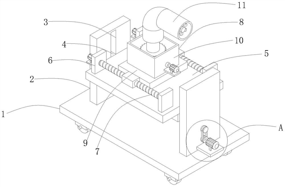
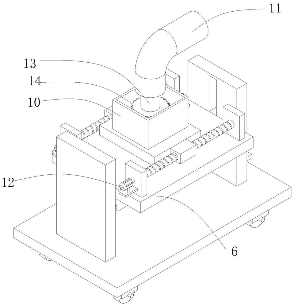
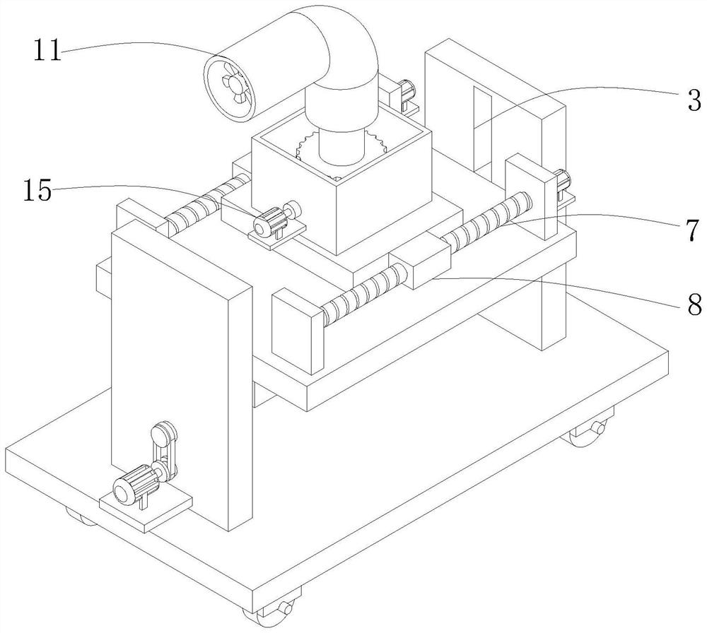
[0045] When using the present invention, first move the equipment to the corresponding position, fix its position by the brake block 22, connect the third motor 26 to the power supply, the third motor 26 drives the driving wheel 27 to rotate, and the driving wheel 27 drives The driven runner 28 is driven by the rotating belt 29 to rotate, so that the two-way threaded column 16 rotates. When the two-way threaded column 16 rotates, the second movable screw sleeve 17 moves laterally, driving the moving rod 18 to move longitudinally, and then drives the longitudinal movement of the moving block 19. Move, the moving block 19 drives the mounting frame plate 5, in the process, the air blower 11 is always in the repeated process of lifting, then the first motor 12 and the second motor 15 are connected to the power supply, and the first motor 12 drives the threaded rod 7 to rotate , so that the first movable screw sleeve 8 moves laterally, thereby causing the blower 11 to move laterally...


PUM


Abstract

The invention discloses a cleaning device for textile machinery, and relates to the technical field of textile machinery cleaning. The cleaning device comprises a mounting bottom plate; a plurality offirst vertical plates are fixedly mounted on the upper surface of the mounting bottom plate; when the number of the first vertical plates is two, a two-way threaded column is arranged between the twofirst vertical plates; a plurality of second movable threaded sleeves are arranged on the peripheral side face of the two-way threaded column, and the number of the second movable threaded sleeves istwo; a movable rod is connected to the upper surface of each second movable threaded sleeve; a movable block is connected to one end of each movable rod; a mounting frame plate is fixedly connected to the upper surfaces of the movable blocks; sliding grooves are formed in the opposite surfaces of the two first vertical plates; sliding plates are mounted in the sliding grooves; and the sliding plates are fixedly connected with the mounting frame plate. The movable blocks are arranged and connected with the mounting frame plate; and when the two-way threaded column rotates, the second movable threaded sleeves transversely move to drive the corresponding movable rods to longitudinally move, then the movable blocks are driven to longitudinally move, the movable blocks drive the mounting frameplate, and lifting of an air blower is facilitated.

Description

technical field [0001] The invention belongs to the technical field of textile machinery cleaning, and in particular relates to a cleaning device for textile machinery and a use method thereof. Background technique [0002] Textile machinery is all kinds of mechanical equipment needed to process natural fibers or chemical fibers into textiles. Although the machinery for producing chemical fibers includes a variety of chemical machinery, it is now considered an extension of textile machinery and belongs to textile machinery in a broad sense. The processes required to process different fibers such as cotton, hemp, silk, wool, etc. into textiles are not the same, and some are completely different, so the machines required are also various and varied. [0003] After the textile machine weaves the cloth, it often leaves some cloth residues. If it is not cleaned up in time, it may cause the cloth residues to block the machine. The traditional textile machinery cleaning device use...

Claims


Application Information

Patent Timeline
Patent Type & Authority Applications(China)
IPC IPC(8): D03J1/00D04B35/32
CPCD03J1/002D04B35/32
Inventor 边疆
Owner 诸暨市惠联精密机械制造有限公司
Why Eureka
Try Eureka