Control method and device for compressor under low current of fuel cell

A fuel cell stack and fuel cell technology, which is applied to fuel cells, electrical components, circuits, etc., can solve problems such as insufficient moisture in the inner membrane of the stack, shorten the service life of the compressor, and increase the power consumption of the compressor, so as to avoid Effects of compressor surge, guaranteed humidity, and reduced power consumption

Active Publication Date: 2021-12-07
BEIJING INSTITUTE OF TECHNOLOGYGY
View PDF16 Cites 0 Cited by
  • Summary
  • Abstract
  • Description
  • Claims
  • Application Information

AI Technical Summary

Problems solved by technology

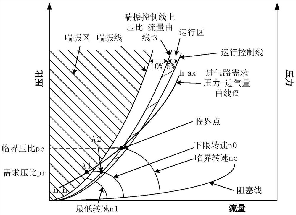
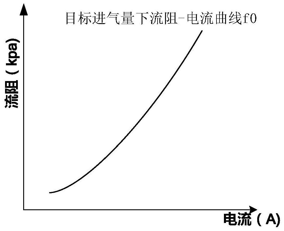
[0005] When the fuel cell system works in the low current stage, the required air flow rate is low, but due to the large flow resistance of the fuel cell stack, a higher intake pressure is required, resulting in the current mainstream centrifugal compressor running in the surge region, reducing the compressor. service life
Although compressor surge can be avoided by increasing the speed of the compressor and increasing the intake pressure and flow rate, there are technical problems: this will also lead to increased power consumption of the compressor and insufficient wetting of the inner membrane of the stack, which will eventually reduce the efficiency of the fuel cell system. reduce
[0011] In this method, when it is judged to be in the preset surge area, the speed of the air compressor and the opening of the air outlet throttle should be adjusted so that the air compressor exits the preset surge area and the fuel consumption must be ensured. The intake pressure and flow of the battery need to increase the speed of the compressor. As mentioned above, the power consumption of the compressor will increase during the low current stage of the fuel cell, which will reduce the efficiency of the fuel cell system

Method used

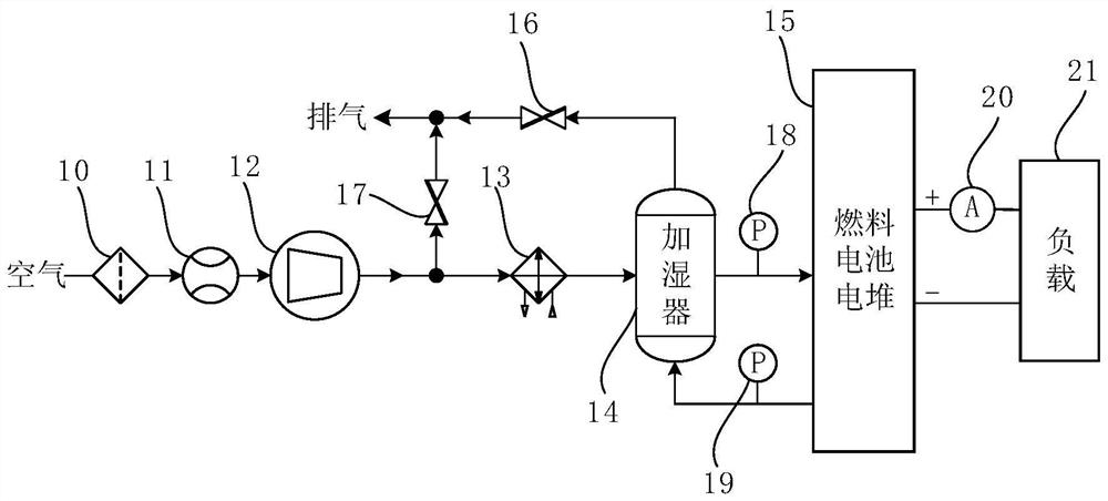

Image

  • Control method and device for compressor under low current of fuel cell
  • Control method and device for compressor under low current of fuel cell
  • Control method and device for compressor under low current of fuel cell

Examples


Embodiment Construction

[0058] The words "first, second, third, etc." or similar terms such as module A, module B, and module C in the description and claims are only used to distinguish similar objects, and do not represent a specific ordering of objects. It can be understood that Obviously, where permitted, the specific order or sequence can be interchanged such that the embodiments of the application described herein can be practiced in other sequences than those illustrated or described herein.

[0059] In the following description, the involved reference numerals representing steps, such as S110, S120, etc., do not mean that this step must be executed, and the order of the previous and subsequent steps can be interchanged or executed simultaneously if allowed.

[0060] The term "comprising" used in the description and claims should not be interpreted as being restricted to what is listed thereafter; it does not exclude other elements or steps. Therefore, it should be interpreted as specifying th...


PUM


Abstract

The present application provides a control method for a compressor under low current of a fuel cell, comprising: obtaining the characteristic curve of the fuel cell stack and the compressor; calculating the critical speed nc of the compressor and the required current Ir corresponding to the The lower limit speed n0; adjust the speed of the compressor from the critical speed nc to the lower limit speed n0, and at each speed during the adjustment process, adjust the opening of the bypass valve and the opening of the back pressure valve, and meet the requirements for the compressor to work in the operating area. Correspondingly, a control device is also provided. This application is applied to when the fuel cell is running in a low current state. By adjusting the speed of the compressor and adjusting the opening of the bypass valve and the back pressure valve, the speed of the compressor can be reduced as much as possible to reduce the pressure of the compressor under the premise of avoiding the surge of the compressor. Power consumption, thereby improving the system efficiency of the fuel cell in the low current phase.

Description

technical field [0001] The present application relates to the technical field of fuel cells, in particular to a control method and device for a compressor of a fuel cell under low current. Background technique [0002] The proton exchange membrane fuel cell system is a device that can directly convert the chemical energy of reactants into electrical energy through electrochemical means. It has the advantages of high efficiency and zero emission, and is considered to be one of the important directions for the sustainable development of the future automobile industry. [0003] The efficiency of the fuel cell system is mainly determined by the efficiency of the fuel cell stack and the power of the auxiliary system mainly based on the power of the compressor. The efficiency of the fuel cell stack is also affected by parameters such as the flow rate, pressure and humidity of the air provided by the compressor. The efficiency of the compressor is affected to a certain extent by th...

Claims


Application Information

Patent Timeline
Patent Type & Authority Patents(China)
IPC IPC(8): H01M8/04746H01M8/04992
CPCH01M8/04753H01M8/04776H01M8/04783H01M8/04992Y02E60/50Y02P70/50
Inventor 韩恺王萱宇李小龙谭红霞冶兆年
Owner BEIJING INSTITUTE OF TECHNOLOGYGY
Why Eureka
Try Eureka